


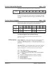

The Input Configuration Registers
The input configuration registers are used to set the following digitizer input
parameters:
• Input enable
• Input impedance
• Input filter
• Measurement range
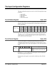
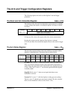
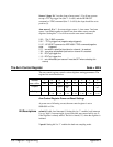
The A/D Status Register base +03
16
The A/D status register is a read only register that returns the status of the
digitizer’s input section. The register bits are defined below. Only the use of
bit 0 is documented.
Address 7 6 5 4 3210
base + 03
16
Ch. 2 Diff.
ovld
Ch. 1 Diff.
ovld
Ch2. S/E
ovld
Ch1. S/E
ovld
unused Ovld
clr
Error
LED
Bit State
0 - no ovld
1 - ovld
0 - no ovld
1 - ovld
0 - no ovld
1 - ovld
0 - no ovld
1 - ovld
--- 0 - OFF
1 - ON
out data
The state (’1’ or ’0’) of bit 0 represents the state of the A/D shift register’s
output bit (bit 55). A read of the status register (and the output bit) does not
cause a shift of the A/D shift register.
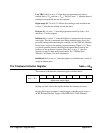
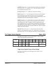
The A/D Serial Register base +05
16
The A/D serial register is a read/write register that receives and sends
configuration data from/to the A/D shift register. The shift register is used
to enable the inputs, and to set the input impedance, filter, and measurement
range.
Address 7 654321 0
base + 05
16
unused register write: shifts one bit into the shift
register
register read: reads one bit out of the shift
register
Each time a ’1’ or ’0’ is written to the serial register, one bit is loaded into
the A/D shift register at bit position 0.
Each time the serial register is read, one bit is shifted out of the A/D shift
register.
350 Register Programming Appendix C