


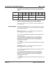
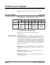
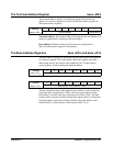

Reference oscillator source: Bits 2 - 0 set the reference oscillator source
from which the sample rate is derived. The sources include:
0 0 0 - the digitizer’s internal 20 MHz oscillator.
0 0 1 - backplane trigger line ECLTrg0.
0 1 0 - backplane trigger line ECLTrg1.
0 1 1 - the EXT2 front panel BNC connector.
1 0 0 - backplane 10 MHz (CLK10) signal.
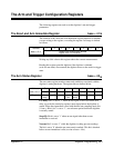
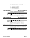
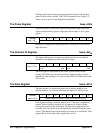
The Arm delay Register base + 51
16
and base +53
16
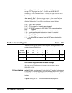
The arm delay is set using the arm delay registers defined below.
Address 76543210
base + 51
16
base + 53
16
base + 51
16
= arm delay most significant byte
base + 53
16
= arm delay least significant byte
Register 51: Contains the most significant byte of the arm delay.
Register 53: Contains the least significant byte of the arm delay.
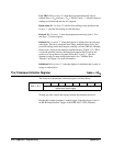
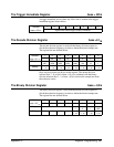
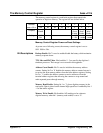
The Arm Count Register base + 55
16
and base + 57
16
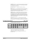
The arm count is set using the arm count registers defined below.
Address 76543210
base + 55
16
base + 57
16
base + 55
16
= arm count most significant byte
base + 57
16
= arm count least significant byte
Register 55: Contains the most significant byte of the arm count.
Register 57: Contains the least significant byte of the arm count.
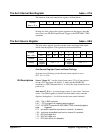
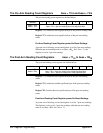
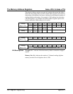
The Arm Count Latch Register base + 59
16
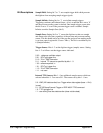
The arm count latch register is used to load the arm count and initialize the
trigger counters. It is written to three times prior to sending the timebase
processor an initiate pulse.
Address 76543210
base + 59
16
register write: loads the arm count and initializes the trigger counters
360 Register Programming Appendix C