


7. Send three clock pulses to the internal high-speed bus by reading or
writing (any value) to the pulse register (base + 08
16
) three times. This
initializes the transfer stages.
8. Set the clock source to the digitizer data register.
A. In the traffic register (base + 02
16
), set the digitizer’s data
register as the high-speed clock source by setting bits 3 - 2 as
indicated:
bits 3 - 2 = 1 0
Setting the data register (base + 0C
16
) as the clock source transfers
a reading from memory to the VME bus each time the data register
is read.
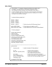
Example Program
The following program demonstrates the procedures used to register
program the digitizer. The program was developed using the
configuration listed on page C-1. To adapt the program for use with
an embedded controller, you will need to change the A24 base
address accordingly, as well as make the modifications noted in the
program listing.
This program accomplishes the following:
• SCPI programming
– configures the digitizer to take 20 readings on the 5V range
using the CONFigure command, and then retrieves the readings
using the READ? command.
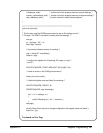
• Register programming
– changes the measurement range to 1V
– changes the trigger source to the reference oscillator period/N
– sets the post-arm reading count to 20 readings
– changes the sample rate to 10 kHz (100 µs)
– re-initiates the digitizer to take the next 20 readings on the 1V
range
– retrieves the readings from memory by reading the data register.
This places the readings on the VME(VXI data transfer) bus.
388 Register Programming Appendix C