


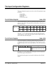


The Arm Internal Bus Register base + 47
16
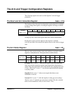
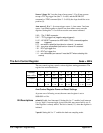
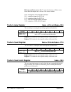
The function of the arm internal bus register is defined below.
Address 76543210
base + 47
16
register write: arm trigger
Writing any 8-bit value to the register generates an arm trigger when the
arm source is an HP-IB Group Execute Trigger or the IEEE-488.2 *TRG
command.
The Arm Source Register base + 49
16
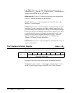
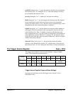
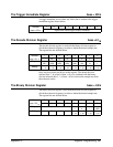
The Arm source register is used to set the source and slope of the signal
which arms the digitizer. The register bits are described below.
Address 7 6 5 4 3 2 1 0
base + 49
16
128
64 32 16 8 4 2 1
Purpose
Source 2
slope
Arm source 2 Source 1
slope
Arm source 1
Setting
0 - positive
1 - negative
0 0 0 - 1 1 1 0 - positive
1 - negative
0 0 0 - 1 1 1
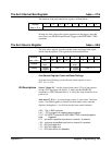
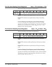
Arm Source Register Power-on/Reset Settings
At power-on or following a reset, the arm source register is set to
0111 1111 or 7F
16
.
Bit Descriptions Source 2 slope: Bit 7 sets the slope of arm source 2. For all arm sources
except a TTLTrg trigger line (bits 6 - 4 =001) and the HP-IB GET
command or *TRG command (bits 6 - 4 =010), the slope should be set to
positive (0).
Arm source 2: Bits 6 - 4 set arm trigger source 2. Arm source 2 and arm
source 1 are ORed together so that an arm from either source arms the
digitizer. Setting bits 6 - 4 as follows sets the arm source indicated.
0 0 0 - "Ext 1" BNC connector.
0 0 1* - TTLTrg trigger line (negative-edge triggered)
0 1 0* - HP-IB GET command or IEEE-488.2 *TRG command(negative
edge triggered)
0 1 1 - arm when a specified input level on channel 1 is reached
1 0 0 - arm when a specified input level on channel 2 is reached
1 0 1 - ECLTrg0 trigger line
1 1 0 - ECLTrg1 trigger line
1 1 1 - OFF (arm source 2 is disabled)
Appendix C Register Programming 355