


The Arm and Trigger Configuration Registers
The following registers are used to set the digitizer’s arm and trigger
parameters.
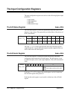
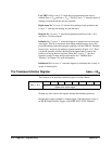
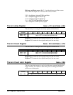
The Abort and Arm Immediate Register base + 41
16
The function of the Abort and Arm Immediate register depends on whether
you are writing to the register, or reading the register. Its useage is defined
as follows
Address 76543210
base + 41
16
register write: measurements aborted
register read: arm immediate
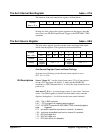
Writing any 8-bit value to this register aborts the current measurements.
Reading this register arms the digitizer if the digitizer is initiated
(wait-for-arm state). Once armed, the digitizer moves to the wait-for-trigger
state.
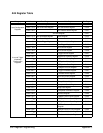
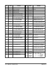
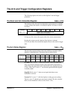
The Arm Status Register base + 43
16
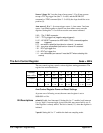
The arm status register monitors states and conditions associated with the
digitizer’s arming hardware. The register bits are defined below.
Address 7 6 5 4 3 2 1 0
base + 43
16
128
64 32 16 8 4 2 1
Purpose
Pre-
delay
Stage2Q No arm Last
TRG*
Begin
samp
Delayed Initiated Initialized
Pre-delay: Bit 7 is set to ’1’ when an arm signal is received, but the arm
delay (as set by the arm delay register) must elapse before the digitizer is
armed. When arm immediate is used with the dual rate sampling mode (bit
5: base + 4B
16
), bit 7 is set to ’1’, one reference period before the digitizer
is actually armed.
Stage2Q: Bit 6 is set to ’1’ when an arm signal other than an arm
immediate is received.
No arm: Bit 5 is set to ’1’ while the digitizer is taking pre-arm readings.
The bit is set to ’0’ when the pre-arm count is reached. This bit is checked
before an arm immediate is sent (a write to base + 41
16
).
Appendix C Register Programming 353