


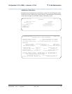
Configuration 2: R7r (+CMS) <—ethernet—> R7csi
91
Administration for Network Connectivity
555-233-504 — Issue 1 — April 2000 CID: 77730
3 C-LAN Administration
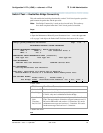
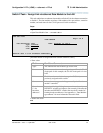
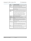
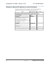
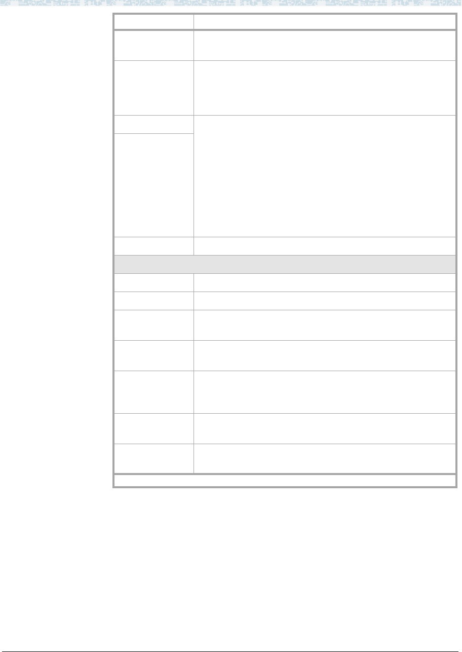
Destination
Node
Name of the far-end node for this channel. This must be a
name entered on the Node Names screen.
Destination Port A value of 0 allows any available interface channel on the
destination node to be used for this connection. The Interface
Channel number on the Switch-2 Processor Channel screen
must also be set to 0.
Session - Local The Local and Remote Session numbers can be any value
between 1 and 256 (si model) or 384 (r model), but they must
be consistent between endpoints. For each connection, the
Local Session number on this switch must equal the Remote
Session number on the remote switch and vice versa.
It is allowed, and sometimes convenient, to use the same
number for the Local and Remote Session numbers. It is
allowed, but not recommended, to use the same Session
numbers for two or more connections.
Session -
Remote
Mach ID This field is not used for CMS.
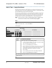
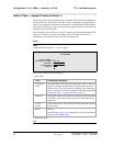
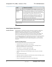
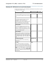
Processor Channel 21: (ethernet connection to Switch 1)
Enable Set to y.
Appl. dcs indicates that this connection will carry DCS data.
Mode Node-5 will be the “client” on this session. Set node-1 (on
Switch 1) to “server” (s).
Interface Link This must match the link number assigned on the node-5 data
module screen.
Interface Chan A value of 0 allows any available interface channel to be used
for this connection. The Destination Port number on the
Switch-1 Processor Channel screen must also be set to 0.
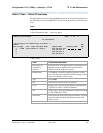
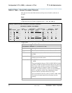
Destination
Node
Name of the far-end node for this channel. This must be a
name entered on the Node Names screen.
Destination Port This number must match the Interface Channel number
assigned on the Switch-1 Processor Channel screen.
Field Conditions/Comments
2 of 3