


Configuration 1: R8r <—ppp—> R8si 3 C-LAN Administration
Administration for Network Connectivity
CID: 77730 555-233-504 — Issue 1 — April 2000
70
Switch 2 Task — Assign Processor Channels
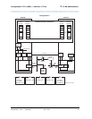
This task associates data links (hardware) with processor channels (software) on
Switch 2.
Begin
Steps
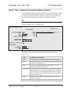
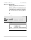
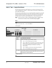
> Open the Processor Channel Assignment form — enter ch com p
> Enter values
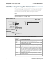
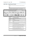
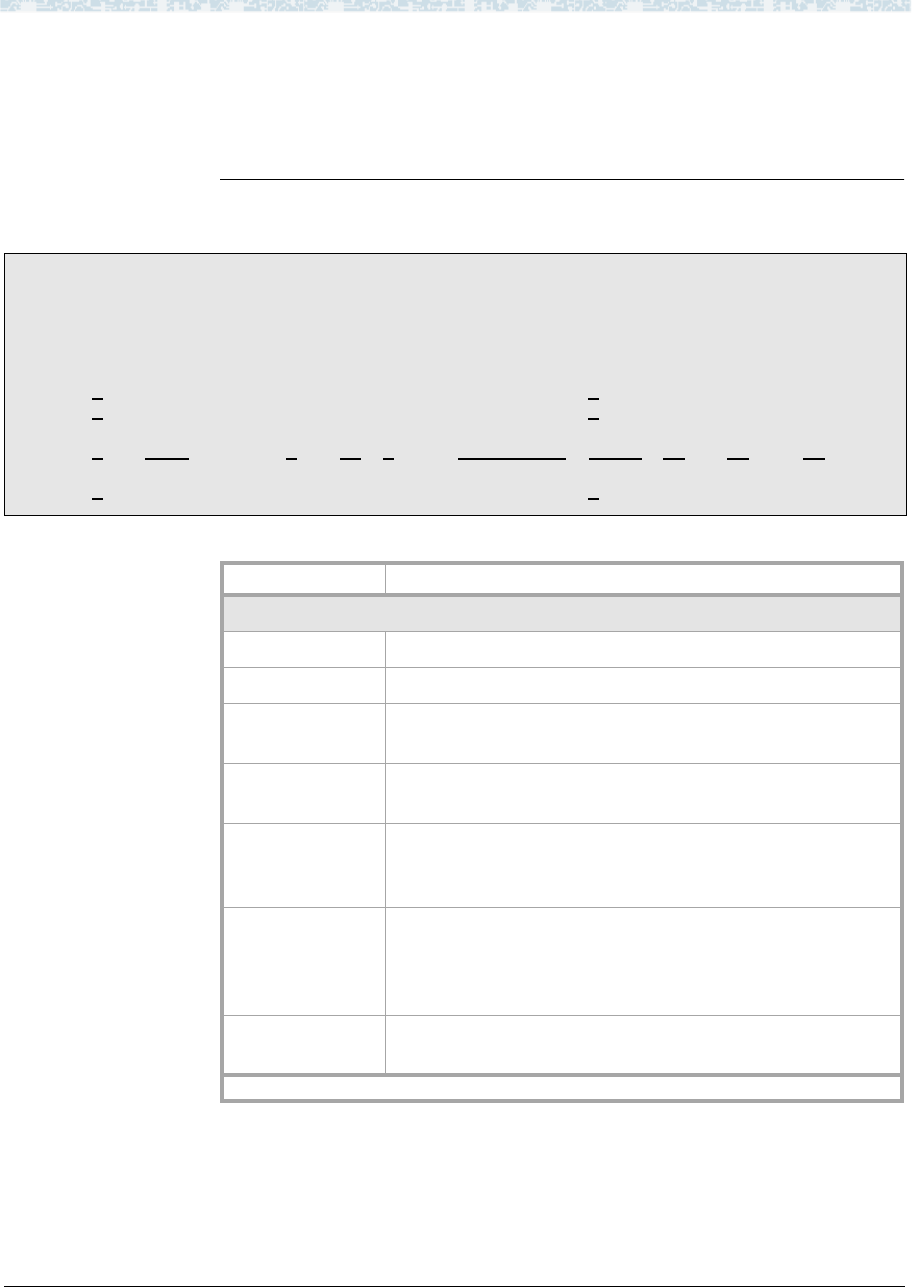
change communications-interface processor-channels
Page 1 of X
PROCESSOR CHANNEL ASSIGNMENT
Proc Gtwy Interface Destination Session Mach
Chan Enable Appl. To Mode Link/Chan Node Port Local/Remote ID
1: n
_______ _ __ _____ __________ 0____ ___ ___ __
2: n
_______ _ __ _____ __________ 0____ ___ ___ __
:
21: y
dcs ___ c 3_ 0____ node-1____ 5003 21_12_ 1_
:
64: n _______ _ __ _____ __________ 0____ ___ ___ __
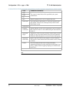
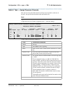
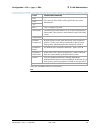
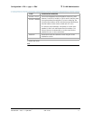
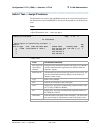
Field Conditions/Comments
Processor Channel 21: (ppp connection to Switch 1)
Enable Set to y.
Appl. Set to dcs for DCS signaling.
Mode Node-2 is the “client” for this session. Set node-1 to “server”
(s).
Interface Link This must match the link number on the node-2 data module
screen in the previous task.
Interface Chan A value of 0 allows any available interface channel to be used
for this connection. The Destination Port number on the
Switch-1 Processor Channel screen must also be set to 0.
Destination Node Name of the far-end node for this channel. This must be a
name entered on the Node Names screen. For ppp
connections, it must match the Destination Node Name
entered on the ppp Data Module screen.
Destination Port This number must match the Interface Channel number
assigned on the Switch-1 Processor Channel screen.
1 of 2