


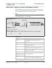
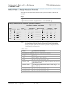
Configuration 3: R8si<—x.25 —> R8r Gateway
<—ethernet—> R8si
3 C-LAN Administration
Administration for Network Connectivity
CID: 77730 555-233-504 — Issue 1 — April 2000
110
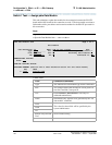
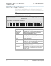
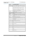
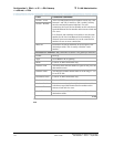
Session - Local The Local and Remote Session numbers can be any value
between 1 and 256 (si model) or 384 (r model), but they must
be consistent between endpoints. For each connection, the
Local Session number on this switch must equal the Remote
Session number on the remote switch and vice versa.
It is allowed, and sometimes convenient, to use the same
number for the Local and Remote Session numbers. It is
allowed, but not recommended, to use the same Session
numbers for two or more connections.
Session - Remote
Mach ID Destination switch ID identified on the dial plan of the
destination switch.
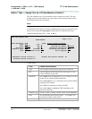
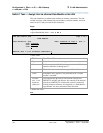
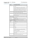
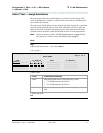
Processor Channel 23: (The X.25 side of the gateway)
Enable Set to y.
Appl. Use gtwy-tcp for conversion between X.25 and TCP/IP.
Gateway To Indicates a software connection between processor channels
23 and 32.
Mode Used for TCP/IP connections only.
Interface Link This must match the link number assigned on the x.25 data
module screen.
Interface Chan The interface channel number must be in the range 1 – 64 for
an X.25 link.
Destination Node Used for TCP/IP connections only.
Destination Port Used for TCP/IP connections only.
Session - Local For each connection, the Local Session number on this switch
must equal the Remote Session number on the remote switch
and vice versa.
Session - Remote
Mach ID Leave blank for gtwy-tcp.
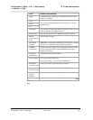
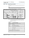
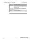
Processor Channel 31: (ethernet connection to Switch 3)
Enable Set to y.
Appl. Set to dcs for DCS signaling.
Mode Node-1 is the “server” for this session. Set node-3 to “client”
(c).
Interface Link This must match the link number assigned on the node-1 data
module screen.
Field Conditions/Comments
2 of 4