


Configuration 5B: R8csi <—ppp—> R8r (2 C-LANs)
<—ethernet—> R8si
3 C-LAN Administration
Administration for Network Connectivity
CID: 77730 555-233-504 — Issue 1 — April 2000
184
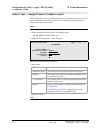
Switch 1 Task — Assign Processor Channels
This task associates data links (hardware) with processor channels (software) on
Switch 1. Note that there are no processor channels or interface channels associated
with the ppp connection between the two C-LAN circuit packs.
Begin
Steps
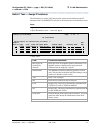
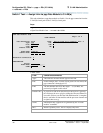
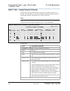
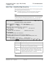
> Open the Processor Channel Assignment form — enter ch com p.
> Enter values
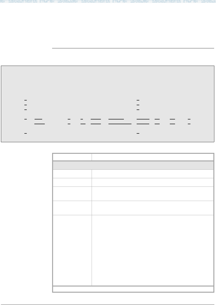
change communications-interface processor-channels
Page 1 of X
PROCESSOR CHANNEL ASSIGNMENT
Proc Gtwy Interface Destination Session Mach
Chan Enable Appl. To Mode Link/Chan Node Port Local/Remote ID
1: n
_______ _ __ _____ _________ 0____ ___ ___ __
2: n
_______ _ __ _____ _________ 0____ ___ ___ __
3: n _______ _ __ _____ _________ 0____ ___ ___ __
:
12: y
dcs____ s 1_ 5003_ node-2___ 0 12_ 21_ 2_
13: y dcs ___ s 2 5003__ node-3___ 0 13_ 31_ 3_
:
384: n
_______ _ __ _____ _________ 0____ ___ ___ __
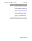
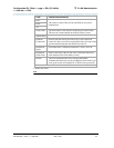
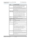
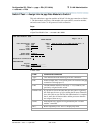
Field Conditions/Comments
Processor Channel 12: (ppp connection to Switch 2)
Enable Set to y.
Appl. Set to dcs for DCS signaling.
Mode Node-1a is the “server” for this session. Set node-2 to “client”
(c).
Interface Link This must match the link number assigned on the node-1a
data module screen.
Interface Chan For TCP/IP, interface channel numbers are in the range 5000
– 64500.
The recommended values are: 5001 for CMS, 5002 for Intuity
AUDIX, and 5003 for DCS connections that are not
gateways. These three values should be reused for multiple
instances of these applications; for example, if there are two
Intuity AUDIX’s, use 5002 for both; or if there are four
DEFINITY ECS’s, use 5003 for all four. The combination of
Link, Interface Channel, and Mach ID must be unique.
This number must match the Destination Port number on the
Switch-2 Processor Channel screen
1 of 3