


203
Administration for Network Connectivity
555-233-504 — Issue 1 — April 2000 CID: 77730
4 Networking Example
This chapter provides an example of a complex network. It describes procedures for
administering trunk groups, dial plans, signaling groups, and data links for a four-switch
network with an Intuity AUDIX and a CMS.
The network example is unchanged from the example in Issue 1 (for R7) of this book. The
screens have been updated for R8.
Overview
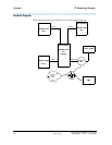
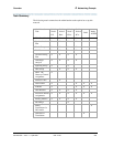
This section shows a high-level diagram of the example network and lists the administration tasks that need to be
completed for each node to set up the network.
NOTE: The term node is used in this chapter, as in the other
chapters, to mean a network interface such as a port
on the C-LAN board. Traditionally, in a DCS network of
DEFINITY switches, node has been used to refer to a
switch.
In this chapter a “DCS node” is referred to as a “Switch
Node.” Thus, a Switch Node (a switch) can have many
nodes (network interfaces).
The Dial Plan and AAR Digit Analysis Table screens
both have fields that still use node to refer to a switch.