


DEFINITY Switch Connectivity 1 Networking Overview
Administration for Network Connectivity
CID: 77730 555-233-504 — Issue 1 — April 2000
4
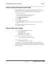
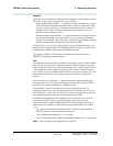
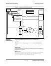
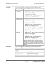
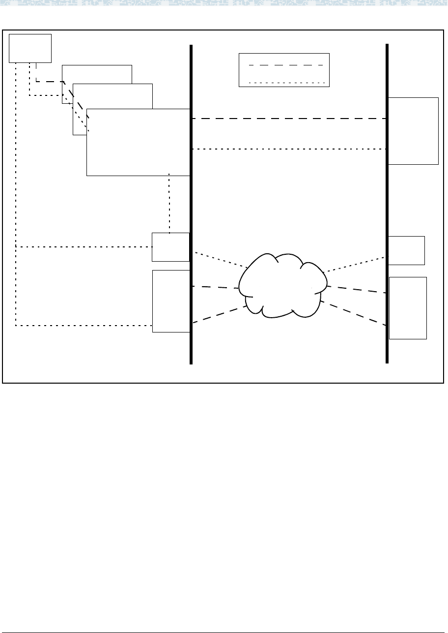
Figure 1. Components of Switch Connectivity
What do the
components do?
The function of each circuit pack shown in Figure 1 is described below.
Processor
The processor board is the main control element in handling the call. This is the
UN332B for the r model, the TN 790B for the si model, and the TN798B for the csi
model.
PGATE (r only)
On the r model, the PGATE board (TN577) connects the processor to the packet bus
and terminates X.25 signaling.
NetPkt (si only)
The Network control/Packet Interface (NetPkt) board (TN794) replaces the NETCON
(TN777B) and the PACCON (TN778) circuit packs in the R7si model. It also
replaces the LAPD portion of the PI (TN765) circuit pack.
PGate (r)
NetPkt (si)
PI (si)
C-LAN
Processor
Signaling Data
Interface to Transmission
Facilities
Tie-Trunk Circuit Packs
DS1, ISDN-PRI, Analog
C-LAN
Tie Trunk
Voice Data
WAN
PPP
DEFINITY
DEFINITY
Switch 2
Switch 1
IP
Interface
MedPro
mode
or
IP trunk
mode
IP
Interface
MedPro
mode
or
IP trunk
mode
LAN
or
10/100BaseT
10BaseT