


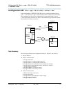
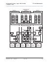
Configuration 5A: R8csi <—ppp—> R8r (one C-LAN)
<—ethernet—> R8si
3 C-LAN Administration
Administration for Network Connectivity
CID: 77730 555-233-504 — Issue 1 — April 2000
168
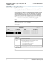
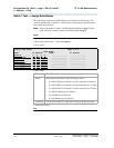
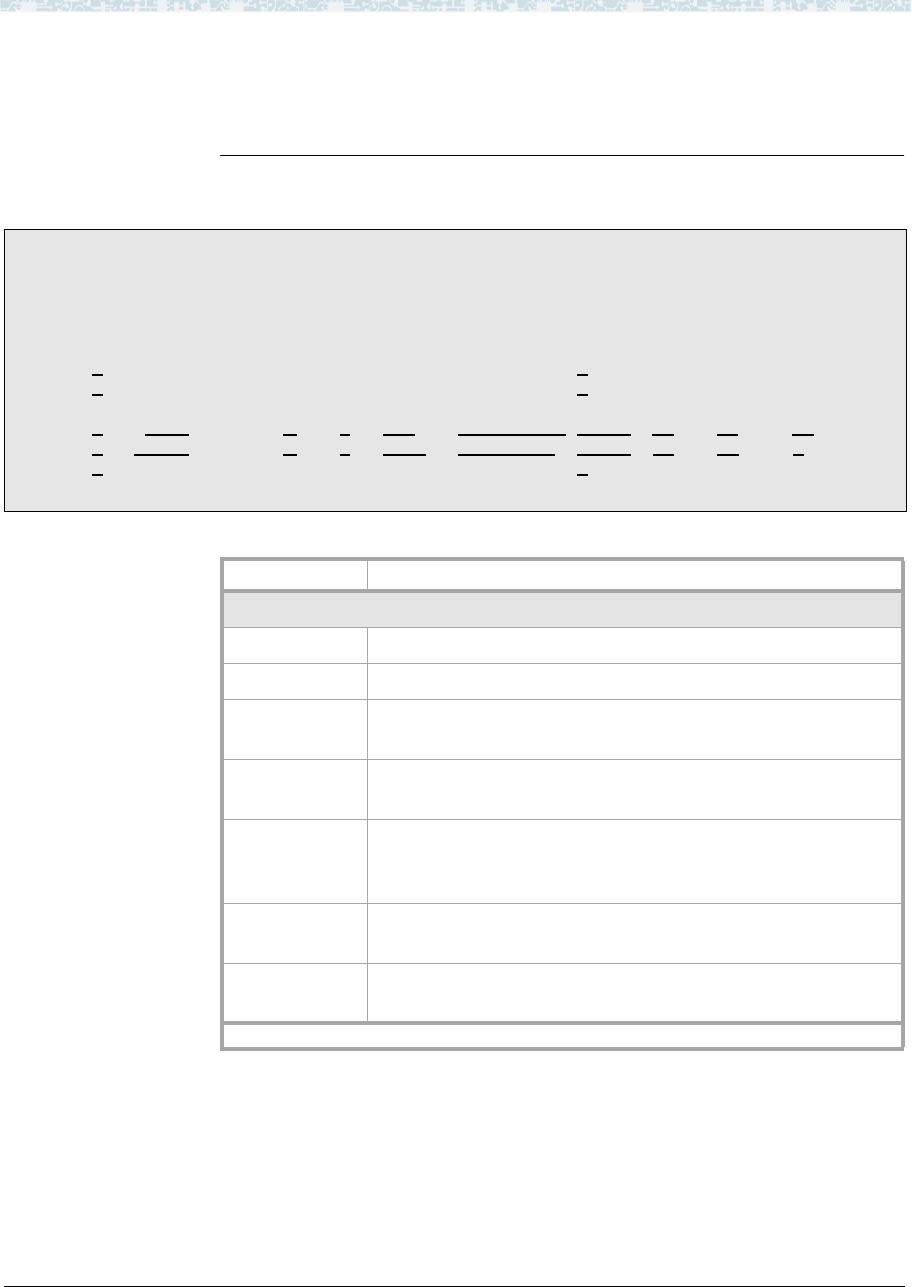
Switch 3 Task — Assign Processor Channels
This task associates data links with processor channels on Switch 3.
Begin
Steps
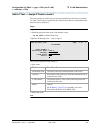
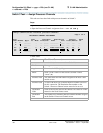
> Open the Processor Channel Assignment form — enter ch com p
> Enter values
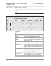
change communications-interface processor-channels
Page 1 of X
PROCESSOR CHANNEL ASSIGNMENT
Proc Gtwy Interface Destination Session Mach
Chan Enable Appl. To Mode Link/Chan Node Port Local/Remote ID
1: n
_______ _ __ _____ _________ 0____ ___ ___ __
2: n
_______ _ __ _____ _________ 0____ ___ ___ __
:
31: y
dcs ___ c 1_ 0 __ node-1-eth 5003_ 31_13__ 1_
32: y dcs ___ s 1_ 5003_ node-2___ 0 32_ 23_ 2_
64: n _______ _ __ _____ _________ 0____ ___ ___ __
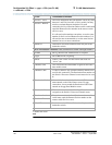
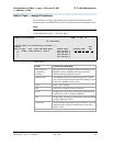
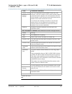
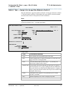
Field Conditions/Comments
Processor Channel 31: (ethernet connection to Switch 1)
Enable Set to y.
Appl. Set to dcs for DCS signaling.
Mode Node-3 is the “client” for this session. Set node-1-eth to
“server” (s).
Interface Link This must match the link number assigned on the node-3 data
module screen.
Interface Chan A value of 0 allows any available interface channel to be used
for this connection. The Destination Port number on the
Switch-1 Processor Channel screen must also be set to 0.
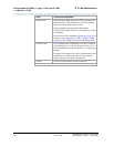
Destination
Node
Name of the far-end node for this channel. This must be a name
entered on the Node Names screen.
Destination
Port
This number must match the Interface Channel number assigned
on the Switch-1 Processor Channel screen.
1 of 2