


IP Addressing 1 Networking Overview
Administration for Network Connectivity
CID: 77730 555-233-504 — Issue 1 — April 2000
26
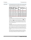
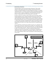
PPP with Ethernet Connections
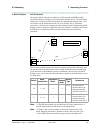
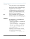
The diagram below shows two interconnected (sub)networks. There are three
switches in a DCS network with a ppp signaling connection between switches A & B
and an ethernet signaling connection between switch A and the adjunct. Switches A
& B and the adjunct are on one (sub)network and switch C is on another
(sub)network.
Switch A acts as a gateway to convert between the two signaling protocols. PPP data
modules are administered between nodes 1 & 3 on switches A & B and ethernet data
modules are administered on switches A & C for the C-LAN ethernet port interfaces
to their LANs. With these connections, switch A can communicate with switch B and
with the adjunct without using the IP Routing screen to administer explicit IP routes.
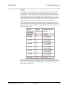
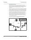
Normally, node 5 would be defined as the default gateway for node 2 on the IP
Interfaces screen, which would enable switch A to communicate with switch C
without an explicit IP route defined. However, if node 5 is not assigned as the default
gateway for node 2, switch A needs an IP route to communicate with switch C
because these switches are on different (sub)networks. Similarly, node 6 would
normally be defined as the default gateway for node 7; if not, switch C needs an IP
route to communicate with switch A.
Also, switch B needs an IP route to communicate with switch C because B is
connected to A via ppp and there are intermediate nodes between B & C.
Wan
or
Intranet
C-LAN
DS1
2
5
6
7
DCS Signaling over Ethernet/ Internet
SW A
SW B
SW C
DCS Signaling over PPP
3
C-LAN
DS1
C-LAN
DS1
Network 2
Network 1
PPP
Ethernet
Ethernet
Adjunct
4
LAN
LAN
1