DEFINITY Switch Connectivity
3
Administration for Network Connectivity
555-233-504 — Issue 1 — April 2000 CID: 77730
1 Networking Overview
TCP/IP signaling connections were introduced with DEFINITY Release 7. Starting
with R7, X.25 was no longer sold with new systems. R7 and later new systems ship
with only TCP/IP connections or ISDN-PRI for DCS signaling. However, existing
systems with X.25 and/or ISDN-PRI DCS signaling can be upgraded to the latest
version and keep those signaling links, or a new system can be added to an existing
DCS network. Connections to the CMS Call Center and Intuity AUDIX adjuncts can
use either X.25 or 10Base-T DCS signaling.
When a DCS network uses a mixture of two or three of the different DCS signaling
types, one or more switches in the network must act as a gateway. A gateway switch
is connected between two switches using different signaling protocols and the
gateway enables the two end switches to communicate by converting the signaling
messages between the two protocols. A gateway switch can provide conversion
between two or all three of the signaling protocols, but only one protocol can be used
for DCS signaling between any two switches.
What is transmitted
between connected
switches?
A telephone call consists of voice (bearer) data and call-signaling data. If the call is
over a DCS network, DCS signaling data is also required. The DCS signaling data is
sent over a separate path from the voice and call-signaling data.
Call-signaling data
The call-signaling data includes messages necessary to set up the call connection,
maintain the connection during the call, and remove the connection when the call is
finished.
DCS-signaling data
The DCS-signaling data is separate from the call-signaling data. How it gets
transmitted depends on the connection type, which determines the type of signaling
protocol used.
How does the data
move between
switches?
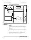
Figure 1 shows some of the major components of switch connections. Before R7, a
call from switch 1 to switch 2, which consists of voice and signaling data, is sent
through a trunk circuit pack across a TDM transmission facility to a trunk circuit pack
in switch 2. Releases 7 and later add alternate pathways for the call data. In R8 and
later releases, Q.931 signaling is used, which enables support for DCS+ and QSIG.
The C-LAN circuit pack enables signaling data to be packetized and sent over a LAN,
WAN, or the Internet. The IP Interface (TN802B) circuit pack enables voice data and
non-DCS signaling data to be sent over IP facilities.


