IP Addressing
25
Administration for Network Connectivity
555-233-504 — Issue 1 — April 2000 CID: 77730
1 Networking Overview
IP Route Examples PPP Connections
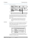
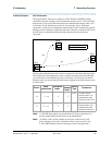
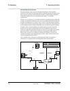
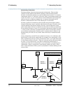
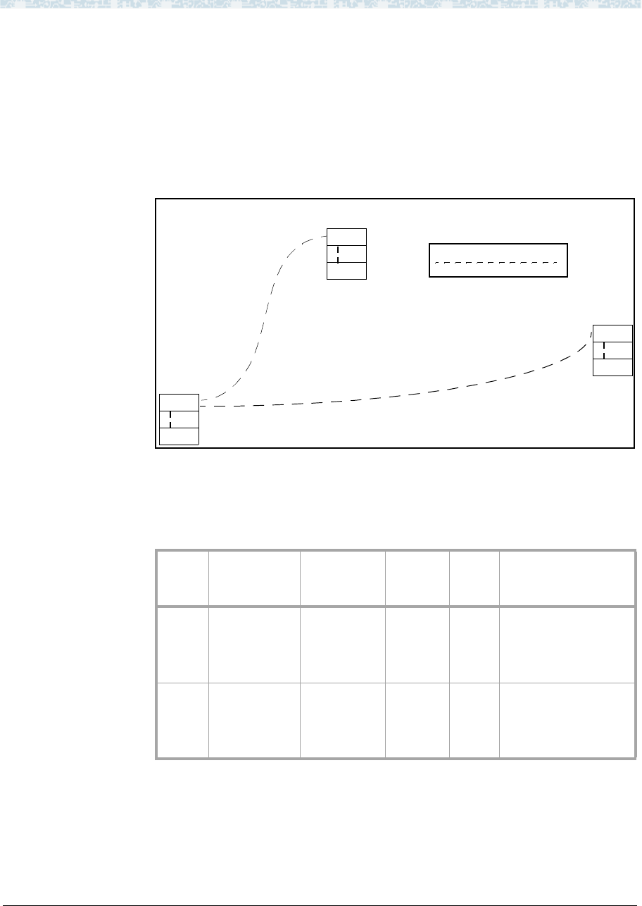
The diagram below shows three switches in a DCS network with PPP signaling
connections between switches A & B and between switches A & C. All nodes in this
diagram are C-LAN ports. PPP data modules are administered between nodes 1 & 2
on switches A & B, and between nodes 3 & 4 on switches A & C. With these
connections, switch A can communicate with switches B and C without using the IP
Routing screen to administer explicit host IP routes. However, switches B and C need
host IP routes to communicate with each other because they are not directly
connected.
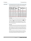
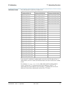
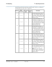
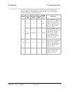
The IP routes needed between nodes for this example are listed in the following table.
The Destination Node and Gateway Node columns in the table show the nodes that
you would enter on the IP Routing screen to administer a host IP route. On the IP
Routing screen, you would enter the node names assigned on the Node Names screen
for these nodes.
Note: (1) The PPP data modules on switches B and C for the connections to A
must be enabled before the IP routes can be administered.
Note: (2) Nodes 2 and 3 in this example are two ports on the same C-LAN
board. Messages from node 1 destined for node 4 arrive at node 2; the
C-LAN ARP software routes the messages to node 4 through node 3.
Switch
Node
Connections
Destination
Node
Gateway
Node
Route
Type
Comments
B 1 —> 4 4 2
host IP route needed
because there is an
intermediate node
between nodes 1 & 4.
C 4 —> 1 1 3
host IP route needed
because there is an
intermediate node
between nodes 4 & 1.
1
4
2
DCS Signaling over PPP
3
SW C
SW A
C-LAN
DS1
C-LAN
DS1
C-LAN
DS1
SW B
ppp
ppp


