


Distributed Communications System
329
Administration for Network Connectivity
555-233-504 — Issue 1 — April 2000 CID: 77730
B Private Networking
Enhanced DCS • Class of Restriction
When a call goes to coverage, it is the called party’s (not the covering party’s)
restrictions that are used.
LWC • DCS Multi-appearance Conference/Transfer
Activation of LWC is denied after a DCS call has been conferenced or transferred.
Multiappearance
Conference/Transfer
• Voice Terminal Display
No display transparency is provided for DCS Multi-Appearance
Conference/Transfer.
• EDCS
On calls to or from Public Network Trunks, calling/called party restrictions are
checked when EDCS is active.
Trunk Group
Busy/Warning
Indication
• Loudspeaker Paging Access
If Trunk Hundreds Select buttons are assigned for Loudspeaker Paging Access
zones, Trunk Group Busy Indicators provide a visual indication of the busy or idle
status of the zones at the remote location as well as at the local node.
Example DCS configurations
The following two examples provide details for setting up two basic DCS networks.
The first is a two-node network and the second is a three-node network. These
examples use BX.25 and D-Channel signaling connections. For examples of TCP/IP
signaling for DCS, see Chapters 2 and 3 in this book.
2-Node private network
with AUDIX
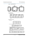
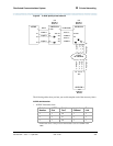
Figure 5 shows a 2-node DCS/AUDIX D-channel network. In this configuration,
DCS feature transparency is achieved exclusively through the exchange of
user-to-user information on the D-channel using one of the three methods discussed
earlier — MA-UUI, CA-TSCs or NCA-TSCs. Although NCA-TSCs are nothing
more than virtual connections on the D-channel, they are shown as independent
entities in the diagram for the purposes of clarity. Administered TSC 2/1 (that is, the
first Administered NCA-TSC of signaling group 2) of Switch A is connected to TSC
4/1 of Switch B. This virtual connection is used in the exchange of user-to-user
information for DCS features not associated with any current B-channel connection.
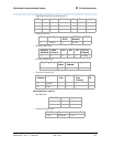
Notice that for AUDIX, a BX.25 data link is no longer required between the host
switch and the remote switch(es). AUDIX messages between the AUDIX and the
remote switch will use the AUDIX Gateway functionality of the host switch and will
be transported to the remote switch via an NCA-TSC. Specifically, AUDIX messages
destined for Switch B will arrive at Switch A on Link 1, Channel 2 (processor channel
57), be converted to ISDN-PRI Q.931 format and sent out via Administered
NCA-TSC 2/2.
This is accomplished by administering processor channel 57 as a gateway and
mapping it on the gateway form to Administered NCA-TSC 2 of signaling group 2
that is also administered as a gateway.