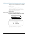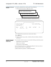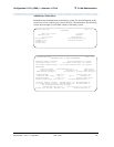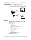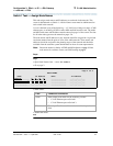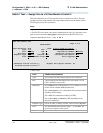
Configuration 2: R7r (+CMS) <—ethernet—> R7csi
97
Administration for Network Connectivity
555-233-504 — Issue 1 — April 2000 CID: 77730
3 C-LAN Administration
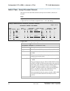
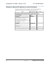
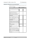
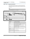
Worksheet B: LAN Data for the Lucent Intuity System
Complete the information on this worksheet to administer the Lucent INTUITY system
for integration with the switch.
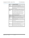
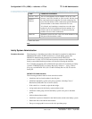
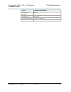
Field Recommended Your Entry
Lucent INTUITY System Switch Interface Administration Window
Extension Length
Use the extension length from the switch dial
plan
4
Host Switch Number
Use 1 if the integration supports only one
DEFINITY switch. If more than one
DEFINITY system will be supported, use the
number administered on the Local Node
Number field in the host switch dial plan.
1
AUDIX Number
The number assigned to the Lucent INTUITY
system on the DEFINITY ECS. For r-model
switches, a number from 1 to 8; for csi and si,
1. This must match the Machine-ID field of the
Processor Channels screen.
1
Switch Number
Enter the node number of the switch being
administered. If there is only one switch,
the value must be
1
. This must match the
Local Node Number field in the switch dial
plan.
1
IP Address/Host Name
Enter the IP address for the switch being
administered.
192.168.1.124
TCP Port
Enter a TCP port number for each Intuity
AUDIX for each switch being administered.
This must match the Interface Channel field of
the Processor Channels screen. You should use
5002 for every switch linked over the LAN in
a DCS network. Use the numbers 6001-6999
for gateway TCP links to remote switches in a
DCS network.
5002


