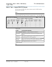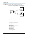
Configuration 4: R8csi <—ISDN—> R8si Gateway
<—ppp—> R8csi
139
Administration for Network Connectivity
555-233-504 — Issue 1 — April 2000 CID: 77730
3 C-LAN Administration
Switch 3 Task — Enable Bus Bridge Connectivity
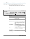
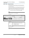
This task enables the bus bridge functionality on the C-LAN circuit pack to provide a
path between the packet bus and the processor.
Note: Bus Bridge Connectivity is used on the csi model only. This task may
have been complete when the C-LAN circuit pack was installed.
Begin
Steps
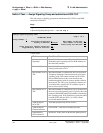
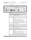
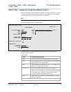
> Open the Maintenance-Related System Parameters form — enter ch sys ma
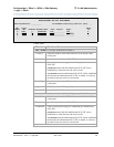
> Go to page 2 and skip to the Packet Intf2? field near the bottom of the screen
> Enter values
> Submit the screen
End
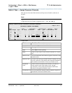
change system-parameters maintenance Page 2 of 3
MAINTENANCE-RELATED SYSTEM PARAMETERS
MINIMUM MAINTENANCE THRESHOLDS ( Before Notification )
TTRs: 4 CPTRs: 1 Call Classifier Ports: 0
MMIs: 0 VCs: 0
TERMINATING TRUNK TRANSMISSION TEST ( Extension )
Test Type 100: Test Type 102: Test Type 105:
ISDN MAINTENANCE
ISDN-PRI Test Call Extension: ISDN-BRI Service SPID:
DS1 MAINTENANCE
DS0 Loop-Around Test Call Extension:
LOSS PLAN ( Leave Blank if no Extra Loss is Required )
Minimum Number of Parties in a Conference Before Adding Extra Loss:
SPE OPTIONAL BOARDS
Packet Intf1? y Packet Intf2? y
Bus Bridge: 01a09__
Inter-Board Link Timeslots Pt0: 6 Pt1: 1 Pt2: 1
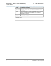
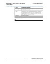
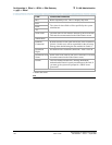
Field Conditions/Comments
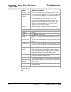
Packet Intf2? Enables the bus bridge.
Bus Bridge: Location of the C-LAN circuit pack. If the system has two
C-LANs, only one is administered for bus bridge.
Inter-Board
Link
Timeslots:
Pt0, Pt1, Pt2
Specifies the bandwidth used on the 3 ports of the Inter-Board
Link. The total number of timeslots assigned cannot exceed 11.
Pt0 carries PPP traffic and can have 1–9 timeslots. Pt1 carries
maintenance messages and can have 1–3 timeslots. Pt2 carries
broadcast messages and can have 1–3 timeslots.


