


DS33R11 Ethernet Mapper with Integrated T1/E1/J1 Transceiver
101 of 344
10.20.2.1 Receive Level Indicator and Threshold Interrupt
The device reports the signal strength at RTIP and RRING in 2.5dB increments through RL3–RL0 located in
Information Register 2 (TR.INFO2). This feature is helpful when trouble-shooting line-performance problems. The
device can initiate an interrupt whenever the input falls below a certain level through the input-level under-threshold
indicator (TR.SR1.7). Using the RLT0–RLT4 bits of the TR.CCR4 register, the user can set a threshold in 2.5dB
increments. The TR.SR1.7 bit is set whenever the input level at RTIP and RRING falls below the threshold set by
the value in RLT0–RLT4. The level must remain below the programmed threshold for approximately 50ms for this
bit to be set. The accuracy of the receive level indication is ±1 LSB (2.5dB) from 25°C to 85°C and ±2 LSBs (5dB)
from –40°C to 25°C.
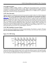
10.20.2.2 Receive G.703 Synchronization Signal (E1 Mode)
The transceiver is capable of receiving a 2.048MHz square-wave synchronization clock as specified in Section 13
of ITU G.703, October 1998. In order to use the device in this mode, set the receive synchronization clock enable
(TR.LIC3.2) = 1.
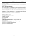
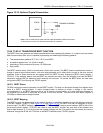
10.20.2.3 Monitor Mode
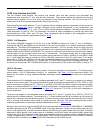
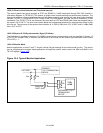
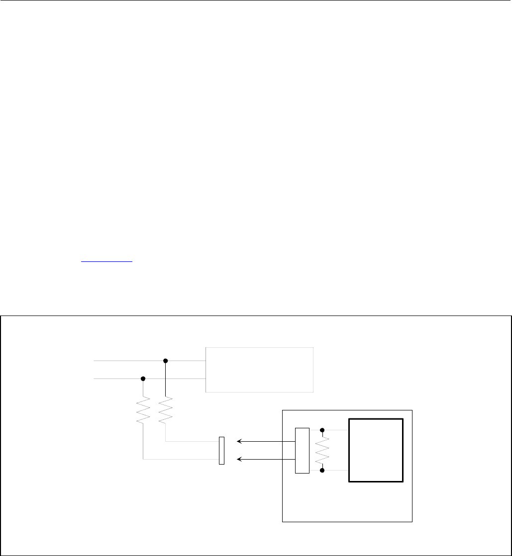
Monitor applications in both E1 and T1 require various flat gain settings for the receive-side circuitry. The device
can be programmed to support these applications through the monitor mode control bits MM1 and MM0 in the
TR.LIC3 register (
Figure 10-5).
Figure 10-5. Typical Monitor Application
PRIMARY
T1/E1 TERMINATING
DEVICE
MONITOR
PORT JACK
T1/E1 LINE
X
F
M
R
T1/E1
XCVR
Rt
Rm Rm
SECONDARY T1/E1
TERMINATING
DEVICE