


DS33R11 Ethernet Mapper with Integrated T1/E1/J1 Transceiver
228 of 344
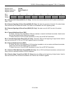
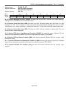
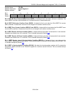
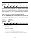
Register Name:
TR.SR8
Register Description:
Status Register 8
Register Address:
24h
Bit # 7 6 5 4 3 2 1 0
Name — — BOCC RFDLAD RFDLF TFDLE RMTCH RBOC
Default 0 0 0 0 0 0 0 0
Bit 5: BOC Clear Event (BOCC). Set when 30 FDL bits occur without an abort sequence.
Bit 4: RFDL Abort Detect Event (RFDLAD). Set when eight consecutive 1s are received on the FDL.
Bit 3: RFDL Register Full Event (RFDLF). Set when the receive FDL buffer (TR.RFDL) fills to capacity.
Bit 2: TFDL Register Empty Event (TFDLE). Set when the transmit FDL buffer (TR.TFDL) empties.
Bit 1: Receive FDL Match Event (RMTCH). Set whenever the contents of the TR.RFDL register matches
TR.RFDLM1 or TR.RFDLM2.
Bit 0: Receive BOC Detector Change-of-State Event (RBOC). Set whenever the BOC detector sees a change of
state to a valid BOC. The setting of this bit prompts the user to read the TR.RFDL register.
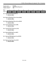
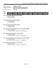
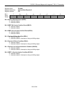
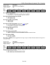
Register Name:
TR.IMR8
Register Description:
Interrupt Mask Register 8
Register Address:
25h
Bit # 7 6 5 4 3 2 1 0
Name — — BOCC RFDLAD RFDLF TFDLE RMTCH RBOC
Default 0 0 0 0 0 0 0 0
Bit 5: BOC Clear Event (BOCC)
0 = interrupt masked
1 = interrupt enabled
Bit 4: RFDL Abort Detect Event (RFDLAD)
0 = interrupt masked
1 = interrupt enabled
Bit 3: RFDL Register Full Event (RFDLF)
0 = interrupt masked
1 = interrupt enabled
Bit 2: TFDL Register Empty Event (TFDLE)
0 = interrupt masked
1 = interrupt enabled
Bit 1: Receive FDL Match Event (RMTCH)
0 = interrupt masked
1 = interrupt enabled
Bit 0: Receive BOC Detector Change-of-State Event (RBOC)
0 = interrupt masked
1 = interrupt enabled