


DS33R11 Ethernet Mapper with Integrated T1/E1/J1 Transceiver
62 of 344
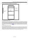
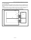
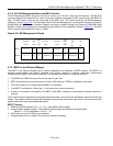
9.15.3 PHY MII Management Block and MDIO Interface
The MII Management Block allows for the host to control up to 32 PHYs, each with 32 registers. The MII block
communicates with the external PHY using 2-wire serial interface composed of MDC (serial clock) and MDIO for
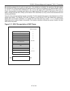
data. The MDIO data is valid on the rising edge of the MDC clock. The Frame format for the MII Management
Interface is shown
Figure 9-8. The read/write control of the MII Management is accomplished through the indirect
SU.MACMIIA MII Management Address Register and data is passed through the indirect SU.MACMIID Data
Register. These indirect registers are accessed through the MAC Control Registers defined in
Table 9-6. The MDC
clock is internally generated and runs at 1.67MHz.
Figure 9-8. MII Management Frame
READ
111...111 01
01
10
01
PHYA[4:0] PHYR[4:0] ZZ
10
ZZZZZZZZZ Z
Z
Preamble Start
Opco
de
Phy Adrs Phy Reg
Turn
Aroun
d
Data
111...111 PHYA[4:0] PHYR[4:0] PHYD[15:0]
32 bits 2 bits
2 bits 5 bits
5 bits
2 bits
16
bits
Idle
1
Bit
WRITE
9.16 BERT in the Ethernet Mapper
The BERT in the Ethernet Mapper can be used for generation and detection of BERT patterns. The BERT is a
software programmable test pattern generator and monitor capable of meeting most error performance
requirements for digital transmission equipment. The following restrictions are related to the BERT:
• The RDEN and TDEN are inputs that can be used to “gap” bits.
• BERT will transmit even when the device is set for X.86 mode and TDEN is configured as an output.
• The normal traffic flow is halted while the BERT is in operation.
• If the BERT is enabled for a Serial port, it will override the normal connection.
• If there is a connection overridden by the BERT, when BERT operation is terminated the normal operation is
restored.
The transmit direction generates the programmable test pattern, and inserts the test pattern payload into the data
stream. The receive direction extracts the test pattern payload from the receive data stream, and monitors the test
pattern payload for the programmable test pattern.
BERT Features
• PRBS and QRSS patterns of 2
9
-1, 2
15
-1 2
23
-1 and QRSS pattern support.
• Programmable repetitive pattern. The repetitive pattern length and pattern are programmable.
[length n = 1 to 32 and pattern = 0 to (2
n
– 1)].
• 24-bit error count and 32-bit bit count registers.
• Programmable bit error insertion. Errors can be inserted individually.