DS33R11 Ethernet Mapper with Integrated T1/E1/J1 Transceiver
234 of 344
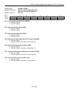
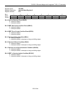
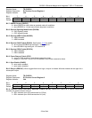
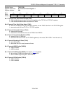
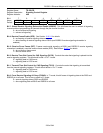
Register Name:
TR.E1RCR1
Register Description:
E1 Receive Control Register 1
Register Address:
33h
Bit # 7 6 5 4 3 2 1 0
Name RSERC RSIGM RHDB3 RG802 RCRC4 FRC SYNCE RESYNC
Default 0 0 0 0 0 0 0 0
Bit 7: RSERO Control (RSERC)
0 = allow RSERO to output data as received under all conditions
1 = force RSERO to 1 under loss-of-frame alignment conditions
Bit 6: Receive Signaling Mode Select (RSIGM)
0 = CAS signaling mode
1 = CCS signaling mode
Bit 5: Receive HDB3 Enable (RHDB3)
0 = HDB3 disabled
1 = HDB3 enabled
Bit 4: Receive G.802 Enable (RG802). See Section 10.10 for details.
0 = do not force RCHBLK high during bit 1 of time slot 26
1 = force RCHBLK high during bit 1 of time slot 26
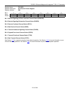
Bit 3: Receive CRC4 Enable (RCRC4)
0 = CRC4 disabled
1 = CRC4 enabled
Bit 2: Frame Resync Criteria (FRC)
0 = resync if FAS received in error three consecutive times
1 = resync if FAS or bit 2 of non-FAS is received in error three consecutive times
Bit 1: Sync Enable (SYNCE)
0 = auto resync enabled
1 = auto resync disabled
Bit 0: Resync (RESYNC). When toggled from low to high, a resync is initiated. Must be cleared and set again for a
subsequent resync.
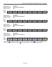
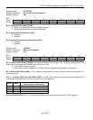
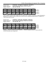
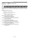
Register Name:
TR.E1RCR2
Register Description:
E1 Receive Control Register 2
Register Address:
34h
Bit # 7 6 5 4 3 2 1 0
Name — — — — — — — RCLA
Default 0 0 0 0 0 0 0 0
Bit 0: Receive Carrier-Loss (RCL) Alternate Criteria (RCLA). Defines the criteria for a receive carrier-loss
condition for both the framer and LIU.
0 = RCL declared upon 255 consecutive 0s (125μs)
1 = RCL declared upon 2048 consecutive 0s (1ms)


