


DS33R11 Ethernet Mapper with Integrated T1/E1/J1 Transceiver
59 of 344
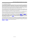
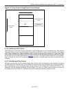
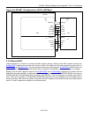
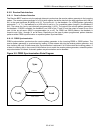
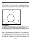
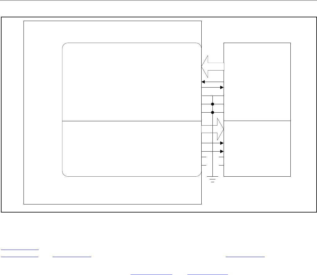
Figure 9-6. DS33R11 Configured as a DCE in MII Mode
MAC
TXD[3:0]
RXD[3:0]
TX_CLKRX_CLK
TX_ERRRX_ERR
TX_EN
RX_CRS
COL_DET COL_DET
DTE
DCE
TX_EN
RXDV
MDC
MDIO
TXD[3:0] RXD[3:0]
TX_CLK
DS33Z11
MAC
RX_CLK
RXDV
RX_CRS
MDIO
MDC
Rx Tx
Tx
Rx
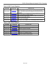
9.15 Ethernet MAC
Indirect addressing is required to access the MAC register settings. Writing to the MAC registers requires the
SU.MACWD0-3 registers to be written with 4 bytes of data. The address for the write operation must be written to
SU.MACAWL and SU.MACAWH. A write command is issued by writing a zero to SU.MACRWC.MCRW and a one
to
SU.MACRWC.MCS (MAC command status). MCS is cleared by the DS33R11 when the operation is complete.
Reading from the MAC registers requires the SU.MACRADH and SU.MACRADL registers to be written with the
address for the read operation. A read command is issued by writing a one to
SU.MACRWC.MCRW and a zero to
SU.MACRWC.MCS. SU.MACRWC.MCS is cleared by the DS33R11 when the operation is complete. After MCS is
clear, valid data is available in
SU.MACRD0-SU.MACRD3. Note that only one operation can be initiated (read or
write) at one time. Data cannot be written or read from the MAC registers until the MCS bit has been cleared by the
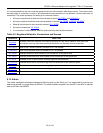
device. The MAC registers are detailed in the following table.