


DS33R11 Ethernet Mapper with Integrated T1/E1/J1 Transceiver
206 of 344
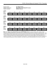
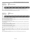
Register Name:
TR.T1TCR1
Register Description:
T1 Transmit Control Register 1
Register Address:
05h
Bit # 7 6 5 4 3 2 1 0
Name TJC TFPT TCPT TSSE GB7S TFDLS TBL TYEL
Default 0 0 0 0 0 0 0 0
Bit 7: Transmit Japanese CRC6 Enable (TJC)
0 = use ANSI/AT&T/ITU CRC6 calculation (normal operation)
1 = use Japanese standard JT–G704 CRC6 calculation
Bit 6: Transmit F-Bit Pass-Through (TFPT)
0 = F bits sourced internally
1 = F bits sampled at TSERI
Bit 5: Transmit CRC Pass-Through (TCPT)
0 = source CRC6 bits internally
1 = CRC6 bits sampled at TSERI during F-bit time
Bit 4: Transmit Software Signaling Enable (TSSE).
0 = do not source signaling data from the TR.TSx registers regardless of the TR.SSIEx registers. The
TR.SSIEx registers still define which channels are to have B7 stuffing preformed.
1 = source signaling data as enabled by the TR.SSIEx registers
Bit 3: Global Bit 7 Stuffing (GB7S)
0 = allow the SSIEx registers to determine which channels containing all 0s are to be bit 7 stuffed
1 = force bit 7 stuffing in all 0-byte channels regardless of how the TR.SSIEx registers are programmed
Bit 2: TFDL Register Select (TFDLS)
0 = source FDL or Fs-bits from the internal TR.TFDL register (legacy FDL support mode)
1 = source FDL or Fs-bits from the internal HDLC controller
Bit 1: Transmit Blue Alarm (TBL)
0 = transmit data normally
1 = transmit an unframed all-ones code at TPOS and TNEG
Bit 0: Transmit Yellow Alarm (TYEL)
0 = do not transmit yellow alarm
1 = transmit yellow alarm