


DS33R11 Ethernet Mapper with Integrated T1/E1/J1 Transceiver
297 of 344
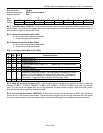
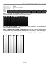
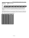
Register Name:
TR.ERC
Register Description:
Error-Rate Control Register
Register Address:
EBh
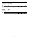
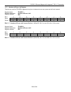
Bit # 7 6 5 4 3 2 1 0
Name WNOE — — CE ER3 ER2 ER1 ER0
Default 0 0 0 0 0 0 0 0
Bit 7: Write NOE Registers (WNOE). If the host wishes to update to the TR.NOEx registers, this bit must be
toggled from a 0 to a 1 after the host has already loaded the prescribed error count into the TR.NOEx registers.
The toggling of this bit causes the error count loaded into the TR.NOEx registers to be loaded into the error-
insertion circuitry on the next clock cycle. Subsequent updates require that the WNOE bit be set to 0 and then 1
once again.
Bit 4: Constant Errors (CE). When this bit is set high (and the ER0 to ER3 bits are not set to 0000), the error-
insertion logic ignores the number-of-error registers (TR.NOE1, TR.NOE2) and generates errors constantly at the
selected insertion rate. When CE is set to 0, the TR.NOEx registers determine how many errors are to be inserted.
Bits 0 – 3: Error-Insertion Rate Select Bits (ER0 to ER3)
ER3 ER2 ER1 ER0 Error Rate
0 0 0 0 No errors inserted
0 0 0 1 1 in 16
0 0 1 0 1 in 32
0 0 1 1 1 in 64
0 1 0 0 1 in 128
0 1 0 1 1 in 256
0 1 1 0 1 in 512
0 1 1 1 1 in 1024
1 0 0 0 1 in 2048
1 0 0 1 1 in 4096
1 0 1 0 1 in 8192
1 0 1 1 1 in 16,384
1 1 0 0 1 in 32,768
1 1 0 1 1 in 65,536
1 1 1 0 1 in 131,072
1 1 1 1 1 in 262,144