


DS33R11 Ethernet Mapper with Integrated T1/E1/J1 Transceiver
237 of 344
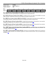
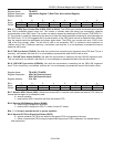
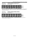
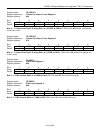
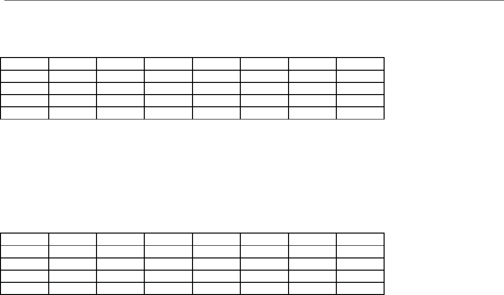
Register Name:
TR.RSINFO1, TR.RSINFO2, TR.RSINFO3, TR.RSINFO4
Register Description:
Receive Signaling Change-of-State Information
Register Address:
38h, 39h, 3Ah, 3Bh
(MSB)
(LSB)
CH8 CH7 CH6 CH5 CH4 CH3 CH2 CH1 RSINFO1
CH16 CH15 CH14 CH13 CH12 CH11 CH10 CH9 RSINFO2
CH24 CH23 CH22 CH21 CH20 CH19 CH18 CH17 RSINFO3
CH30 CH29 CH28 CH27 CH26 CH25 RSINFO4
When a channel’s signaling data changes state, the respective bit in registers TR.RSINFO1–4 is set. An interrupt is
generated if the channel was also enabled as an interrupt source by setting the appropriate bit in TR.RSCSE1–4.
The bit remains set until read.
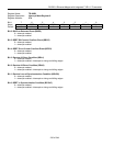
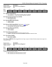
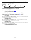
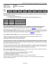
Register Name:
TR.RSCSE1, TR.RSCSE2, TR.RSCSE3, TR.RSCSE4
Register Description:
Receive Signaling Change-of-State Interrupt Enable
Register Address:
3Ch, 3Dh, 3Eh, 3Fh
(MSB)
(LSB)
CH8 CH7 CH6 CH5 CH4 CH3 CH2 CH1 RSCSE1
CH16 CH15 CH14 CH13 CH12 CH11 CH10 CH9 RSCSE2
CH24 CH23 CH22 CH21 CH20 CH19 CH18 CH17 RSCSE3
CH30 CH29 CH28 CH27 CH26 CH25 RSCSE4
Setting any of the CH1–CH30 bits in the TR.RSCSE1– TR.RSCSE4 registers causes an interrupt when that
channel’s signaling data changes state.