


DS33R11 Ethernet Mapper with Integrated T1/E1/J1 Transceiver
241 of 344
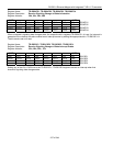
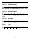
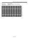
Register Name:
TR.FOSCR1
Register Description:
Frames Out-of-Sync Count Register 1
Register Address:
46h
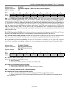
Bit # 7 6 5 4 3 2 1 0
Name FOS15 FOS14 FOS13 FOS12 FOS11 FOS10 FOS9 FOS8
Default 0 0 0 0 0 0 0 0
Bits 0 – 7: Frames Out-of-Sync Counter Bits 8 to 15 (FOS8 to FOS15). FOS15 is the MSB of the 16-bit frames
out-of-sync count.
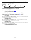
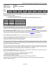
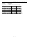
Register Name:
TR.FOSCR2
Register Description:
Frames Out-of-Sync Count Register 2
Register Address:
47h
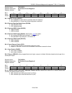
Bit # 7 6 5 4 3 2 1 0
Name FOS7 FOS6 FOS5 FOS4 FOS3 FOS2 FOS1 FOS0
Default 0 0 0 0 0 0 0 0
Bits 0 – 7: Frames Out-of-Sync Counter Bits 0 to 7 (FOS0 to FOS7). FOS0 is the LSB of the 16-bit frames out-
of-sync count.
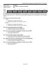
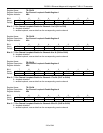
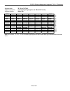
Register Name:
TR.EBCR1
Register Description:
E-Bit Count Register 1
Register Address:
48h
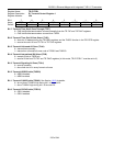
Bit # 7 6 5 4 3 2 1 0
Name EB15 EB14 EB13 EB12 EB11 EB10 EB9 EB8
Default 0 0 0 0 0 0 0 0
Bits 0 – 7: E-Bit Counter Bits 8 to 15 (EB8 to EB15). EB15 is the MSB of the 16-bit E-bit count.
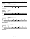
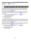
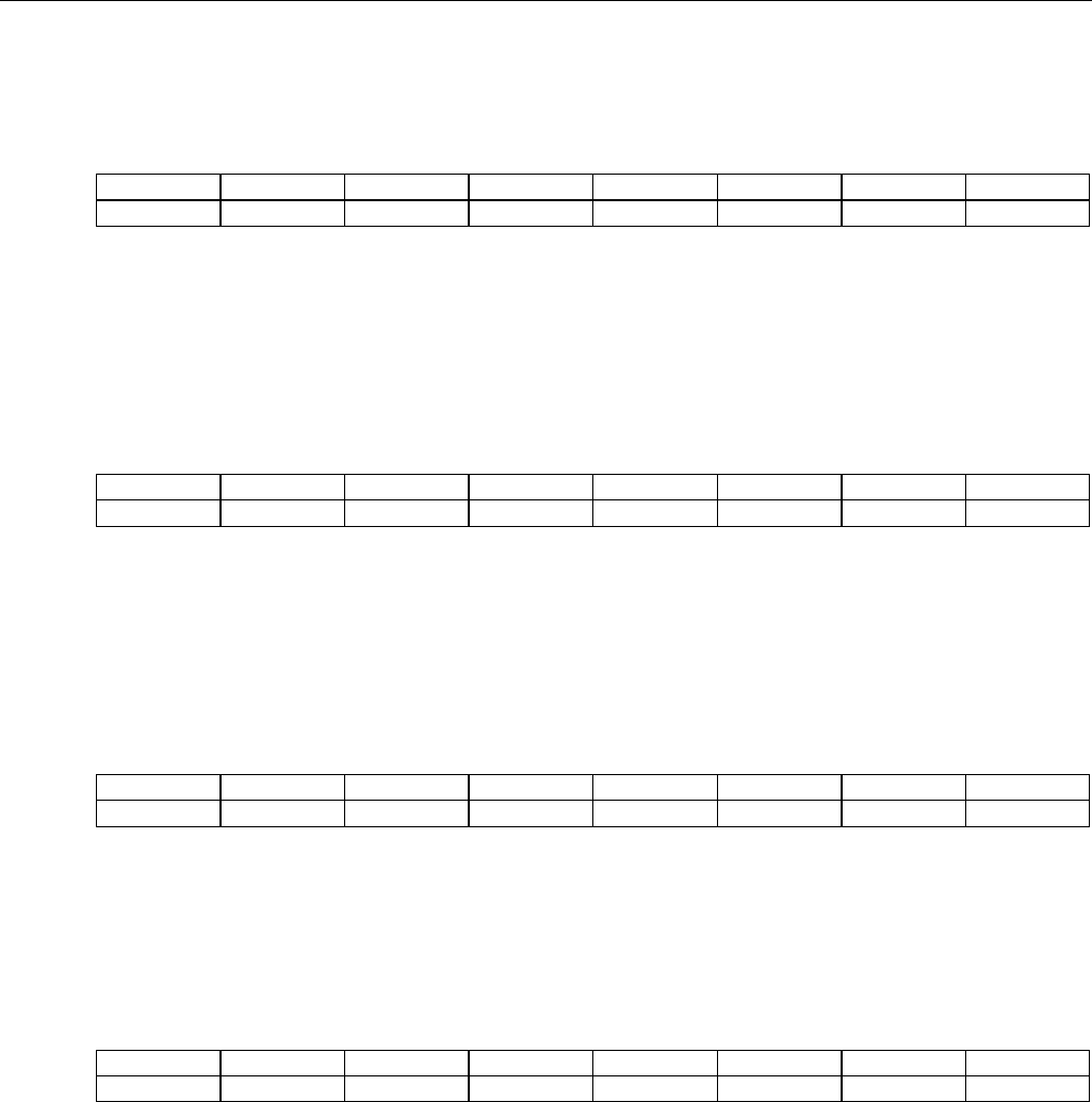
Register Name:
TR.EBCR2
Register Description:
E-Bit Count Register 2
Register Address:
49h
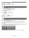
Bit # 7 6 5 4 3 2 1 0
Name EB7 EB6 EB5 EB4 EB3 EB2 EB1 EB0
Default 0 0 0 0 0 0 0 0
Bits 0 – 7: E-Bit Counter Bits 0 to 7 (EB0 to EB7). EB0 is the LSB of the 16-bit E-bit count.