


DS33R11 Ethernet Mapper with Integrated T1/E1/J1 Transceiver
169 of 344
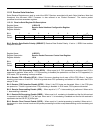
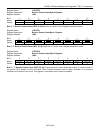
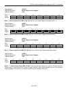
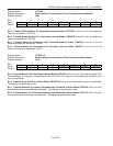
Register Name:
LI.RBC0
Register Description:
Receive Byte Count 0 Register
Register Address:
118h
Bit # 7 6 5 4 3 2 1 0
Name RBC7 RBC6 RBC5 RBC4 RBC3 RBC2 RBC1 RBC0
Default 0 0 0 0 0 0 0 0
Bits 0 - 7: Receive Byte Count (RBC [7:0]) Eight bits of a 32-bit value. Register description below.
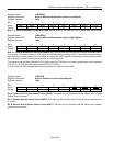
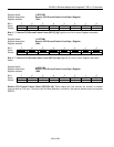
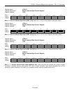
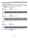
Register Name:
LI.RBC1
Register Description:
Receive Byte Count 1 Register
Register Address:
119h
Bit # 7 6 5 4 3 2 1 0
Name
RBC15 RBC14 RBC13 RBC12 RBC11 RBC10 RBC9 RBC8
Default 0 0 0 0 0 0 0 0
Bits 0 - 7: Receive Byte Count (RBC [15:8]) Eight bits of a 32-bit value. Register description below.
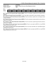
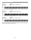
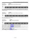
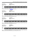
Register Name:
LI.RBC2
Register Description:
Receive Byte Count 2 Register
Register Address:
11Ah
Bit # 7 6 5 4 3 2 1 0
Name
RBC23 RBC22 RBC21 RBC20 RBC19 RBC18 RBC17 RBC16
Default 0 0 0 0 0 0 0 0
Bits 0 - 7: Receive Byte Count (RBC [23:16]) Eight bits of a 32-bit value. Register description below.
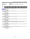
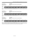
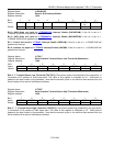
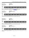
Register Name:
LI.RBC3
Register Description:
Receive Byte Count 3 Register
Register Address:
11Bh
Bit # 7 6 5 4 3 2 1 0
Name
RBC31 RBC30 RBC29 RBC28 RBC27 RBC26 RBC25 RBC24
Default 0 0 0 0 0 0 0 0
Bits 0 – 7: Receive Byte Count (RBC [31:24]) These thirty-two bits indicate the number of bytes contained in
packets stored in the receive FIFO without an abort indication. Note: Bytes discarded due to FCS extraction,
system loopback, FIFO reset, or an overflow condition may be included in this count.