


DS33R11 Ethernet Mapper with Integrated T1/E1/J1 Transceiver
230 of 344
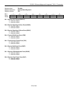
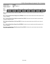
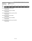
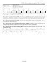
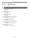
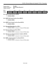
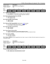
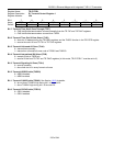
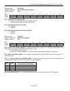
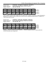
Register Name:
TR.IMR9
Register Description:
Interrupt Mask Register 9
Register Address:
27h
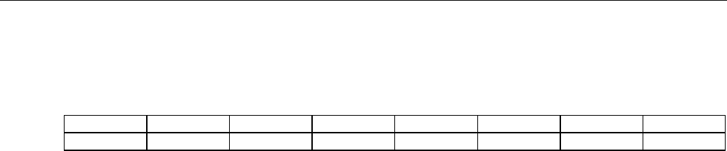
Bit # 7 6 5 4 3 2 1 0
Name — BBED BBCO BEC0 BRA1 BRA0 BRLOS BSYNC
Default 0 0 0 0 0 0 0 0
Bit 6: Bit-Error Detected Event (BBED)
0 = interrupt masked
1 = interrupt enabled
Bit 5: BERT Bit-Counter Overflow Event (BBCO)
0 = interrupt masked
1 = interrupt enabled
Bit 4: BERT Error-Counter Overflow Event (BECO)
0 = interrupt masked
1 = interrupt enabled
Bit 3: Receive All-Ones Condition (BRA1)
0 = interrupt masked
1 = interrupt enabled—interrupts on rising and falling edges
Bit 2: Receive All-Zeros Condition (BRA0)
0 = interrupt masked
1 = interrupt enabled—interrupts on rising and falling edges
Bit 1: Receive Loss-of-Synchronization Condition (BRLOS)
0 = interrupt masked
1 = interrupt enabled—interrupts on rising and falling edges
Bit 0: BERT in Synchronization Condition (BSYNC)
0 = interrupt masked
1 = interrupt enabled—interrupts on rising and falling edges