


DS33R11 Ethernet Mapper with Integrated T1/E1/J1 Transceiver
210 of 344
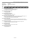
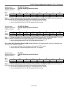
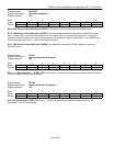
Register Name:
TR.SSIE3 (T1 Mode)
Register Description:
Software Signaling-Insertion Enable 3
Register Address:
0Ah
Bit # 7 6 5 4 3 2 1 0
Name CH24 CH23 CH22 CH21 CH20 CH19 CH18 CH17
Default 0 0 0 0 0 0 0 0
Bits 0 – 7: Software Signaling Insertion Enable for Channels 17 to 24 (CH17 to CH24). These bits determine
which channels are to have signaling inserted from the transmit signaling registers.
0 = do not source signaling data from the TR.TSx registers for this channel
1 = source signaling data from the TR.TSx registers for this channel
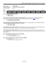
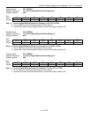
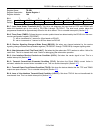
Register Name:
TR.SSIE3 (E1 Mode)
Register Description:
Software Signaling Insertion Enable 3
Register Address:
0Ah
Bit # 7 6 5 4 3 2 1 0
Name CH22 CH21 CH20 CH19 CH18 CH17 CH16 LCAW
Default 0 0 0 0 0 0 0 0
Bits 1 – 7: Software Signaling Insertion Enable for LCAW and Channels 16 to 22 (CH16 to CH22). These bits
determine which channels are to have signaling inserted from the transmit signaling registers.
0 = do not source signaling data from the TR.TSx registers for this channel
1 = source signaling data from the TR.TSx registers for this channel
Bit 0: Lower CAS Align/Alarm Word (LCAW). Selects the lower CAS align/alarm bits (xyxx) to be sourced from
the lower 4 bits of the TS1 register.
0 = do not source the lower CAS align/alarm bits from the TR.TS1 register
1 = source the lower CAS alarm align/bits from the TR.TS1 register
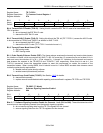
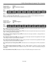
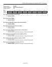
Register Name:
TR.SSIE4
Register Description:
Software Signaling Insertion Enable 4
Register Address:
0Bh
Bit # 7 6 5 4 3 2 1 0
Name CH30 CH29 CH28 CH27 CH26 CH25 CH24 CH23
Default 0 0 0 0 0 0 0 0
Bits 0 – 7: Software Signaling Insertion Enable for Channels 22 to 30 (CH23 to CH30). These bits determine
which channels are to have signaling inserted from the transmit signaling registers.
0 = do not source signaling data from the TR.TSx registers for this channel
1 = source signaling data from the TR.TSx registers for this channel