


DS33R11 Ethernet Mapper with Integrated T1/E1/J1 Transceiver
216 of 344
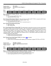
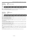
Register Name:
TR.IMR1
Register Description:
Interrupt Mask Register 1
Register Address:
17h
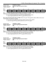
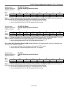
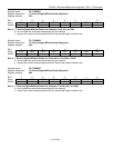
Bit # 7 6 5 4 3 2 1 0
Name ILUT TIMER RSCOS JALT LRCL TCLE TOCD LOLITC
Default 0 0 0 0 0 0 0 0
Bit 7: Input Level Under Threshold (ILUT)
0 = interrupt masked
1 = interrupt enabled
Bit 6: Timer Event (TIMER)
0 = interrupt masked
1 = interrupt enabled
Bit 5: Receive Signaling Change-of-State Event (RSCOS)
0 = interrupt masked
1 = interrupt enabled
Bit 4: Jitter Attenuator Limit Trip Event (JALT)
0 = interrupt masked
1 = interrupt enabled
Bit 3: Line Interface Receive Carrier-Loss Condition (LRCL)
0 = interrupt masked
1 = interrupt enabled—generates interrupts on rising and falling edges
Bit 2: Transmit Current-Limit Exceeded Condition (TCLE)
0 = interrupt masked
1 = interrupt enabled—generates interrupts on rising and falling edges
Bit 1: Transmit Open-Circuit Detect Condition (TOCD)
0 = interrupt masked
1 = interrupt enabled—generates interrupts on rising and falling edges
Bit 0: Loss-of-Transmit Clock Condition (LOLITC)
0 = interrupt masked
1 = interrupt enabled—generates interrupts on rising and falling edges