


DS33R11 Ethernet Mapper with Integrated T1/E1/J1 Transceiver
212 of 344
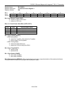
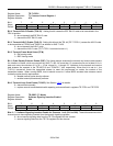
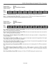
Register Name:
TR.IDR
Register Description:
Device Identification Register
Register Address:
0Fh
Bit # 7 6 5 4 3 2 1 0
Name ID7 ID6 ID5 ID4 ID3 ID2 ID1 ID0
Default 1
0
1 1 X X X X
Bits 4 - 7: Device ID (ID4 to ID7). The upper four bits of TR.IDR are used to display the transceiver ID.
Bits 0 – 3: Chip Revision Bits (ID0 to ID3). The lower four bits of TR.IDR are used to display the die revision of
the chip. IDO is the LSB of a decimal code that represents the chip revision.
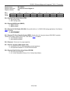
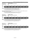
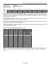
Register Name:
TR.INFO1
Register Description:
Information Register 1
Register Address:
10h
Bit # 7 6 5 4 3 2 1 0
Name RPDV TPDV COFA 8ZD 16ZD SEFE B8ZS FBE
Default 0 0 0 0 0 0 0 0
Bit 7: Receive Pulse-Density Violation Event (RPDV). Set when the receive data stream does not meet the
ANSI T1.403 requirements for pulse density.
Bit 6: Transmit Pulse-Density Violation Event (TPDV). Set when the transmit data stream does not meet the
ANSI T1.403 requirements for pulse density.
Bit 5: Change-of-Frame Alignment Event (COFA). Set when the last resync resulted in a change-of-frame or
multiframe alignment.
Bit 4: Eight Zero-Detect Event (8ZD). Set when a string of at least eight consecutive 0s (regardless of the length
of the string) have been received at RPOSI and RNEGI.
Bit 3: Sixteen Zero-Detect Event (16ZD). Set when a string of at least 16 consecutive 0s (regardless of the length
of the string) have been received at RPOSI and RNEGI.
Bit 2: Severely Errored Framing Event (SEFE). Set when two out of six framing bits (Ft or FPS) are received in
error.
Bit 1: B8ZS Codeword Detect Event (B8ZS). Set when a B8ZS codeword is detected at RPOS and RNEG
independent of whether the B8ZS mode is selected or not by TR.T1TCR2.7. Useful for automatically setting the
line coding.
Bit 0: Frame Bit-Error Event (FBE). Set when an Ft (D4) or FPS (ESF) framing bit is received in error.