


DS33R11 Ethernet Mapper with Integrated T1/E1/J1 Transceiver
327 of 344
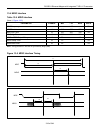
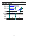
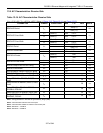
13.9 AC Characteristics: Receive-Side
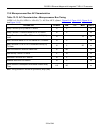
Table 13-14. AC Characteristics: Receive Side
(V
DD
= 3.3V ±5%, T
A
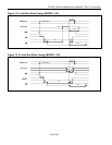
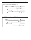
= -40°C to +85°C.) (Note 1, Figure 13-3, Figure 13-14, and Figure 13-15)
PARAMETER SYMBOL CONDITIONS MIN TYP MAX UNITS
488 (E1)
RDCLKO Period t
LP
648 (T1)
ns
t
LH
(Note 2) 200 0.5 t
LP
RDCLKO Pulse Width
t
LL
(Note 2) 200 0.5 t
LP
ns
t
LH
(Note 3) 150 0.5 t
LP
RDCLKO Pulse Width
t
LL
(Note 3) 150 0.5 t
LP
ns
488 (E1)
RDCLKI Period t
CP
648 (T1)
ns
t
CH
20 0.5 t
CP
RDCLKI Pulse Width
t
CL
20 0.5 t
CP
ns
(Note 4) 648
RSYSCLK Period t
SP
(Note 5) 488
ns
t
SH
20 0.5 t
SP
ns
RSYSCLK Pulse Width
t
SL
20 0.5 t
SP
ns
RSYNC Setup to RSYSCLK Falling t
SU
20 ns
RSYNC Pulse Width t
PW
50 ns
RPOSI/RNEGI Setup to RDCLKI Falling t
SU
20 ns
RPOSI/RNEGI Hold from RDCLKI Falling t
HD
20 ns
RSYSCLK, RDCLKI Rise and Fall Times t
R
, t
F
22 ns
Delay RDCLKO to RPOSO, RNEGO
Valid
t
DD
50 ns
Delay RCLKO to RSERO, RDATA, RSIG
Valid
t
D1
50 ns
Delay RCLKO to RCHCLK, RSYNC,
RCHBLK, RFSYNC
t
D2
50 ns
Delay RSYSCLK to RSERO, RSIG Valid t
D3
22 ns
Delay RSYSCLK to RCHCLK, RCHBLK,
RMSYNC, RSYNC
t
D4
22 ns
Note 1: Timing parameters in this table are guaranteed by design (GBD).
Note 2:
Jitter attenuator enabled in the receive path.
Note 3: Jitter attenuator disabled or enabled in the transmit path.
Note 4: RSYSCLK = 1.544MHz.
Note 5: RSYSCLK = 2.048MHz.