


DS33R11 Ethernet Mapper with Integrated T1/E1/J1 Transceiver
95 of 344
10.16.2 FIFO Control
The FIFO control register (TR.HxFC) controls and sets the watermarks for the transmit and receive FIFOs. Bits 3,
4, and 5 set the transmit low watermark and the lower 3 bits set the receive high watermark.
When the transmit FIFO empties below the low watermark, the TLWM bit in the appropriate HDLC status register
TR.SR6 or TR.SR7 is set. TLWM is a real-time bit and remains set as long as the transmit FIFO’s read pointer is
below the watermark. If enabled, this condition can also cause an interrupt through the INT pin.
When the receive FIFO fills above the high watermark, the RHWM bit in the appropriate HDLC status register is
set. RHWM is a real-time bit and remains set as long as the receive FIFO’s write pointer is above the watermark. If
enabled, this condition can also cause an interrupt through the INT pin.
10.16.3 HDLC Mapping
The HDLC controllers must be assigned a space in the T1/E1 bandwidth in which they transmit and receive data.
The controllers can be mapped to either the FDL (T1), Sa bits (E1), or to channels. If mapped to channels, then
any channel or combination of channels, contiguous or not, can be assigned to an HDLC controller. When
assigned to a channel(s), any combination of bits within the channel(s) can be avoided.
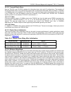
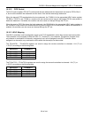
The TR.HxRCS1 – TR.HxRCS4 registers are used to assign the receive controllers to channels 1–24 (T1) or
1–32 (E1) according to the following table:
REGISTER CHANNELS
TR.HxRCS1 1–8
TR.HxRCS2 9–16
TR.HxRCS3 17–24
TR.HxRCS4 25–32
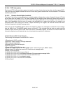
The TR.HxTCS1 – TR.HxTCS4 registers are used to assign the transmit controllers to channels 1–24 (T1) or
1–32 (E1) according to the following table.
REGISTER CHANNELS
TR.HxTCS1 1–8
TR.HxTCS2 9–16
TR.HxTCS3 17–24
TR.HxTCS4 25–32