


DS33R11 Ethernet Mapper with Integrated T1/E1/J1 Transceiver
26 of 344
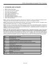
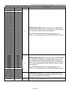
NAME PIN TYPE FUNCTION
RD/DS
B11 I
Read Data Strobe (Intel Mode): The DS33R11 drives the data bus
(D0-D7) with the contents of the addressed register while RD and
CS are both low.
Data Strobe (Motorola Mode): Used to latch data through the
microprocessor interface. DS must be low during read and write
operations.
CS
A11 I
Chip Select for Protocol Conversion Device: This pin must be
taken low for read/write operations. When CS is high, the RD/DS
and WR signals are ignored.
CST
D7 I
Chip Select for the T1/E1/J1 Transceiver: Must be low to read or
write the T1/E1/J1 transceiver.
INT
A10 OZ
Interrupt Output: Outputs a logic zero when an unmasked
interrupt event is detected. INT is deasserted when all interrupts
have been acknowledged and serviced. Active low. Inactive state is
programmable in register
GL.CR1. is deasserted when all
interrupts have been acknowledged and serviced. Active low.
Inactive state is programmable in register
GL.CR1.