


DS33R11 Ethernet Mapper with Integrated T1/E1/J1 Transceiver
154 of 344
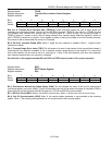
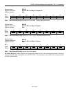
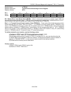
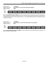
Register Name:
LI.TEPHC
Register Description:
Transmit Errored Packet High Control Register
Register Address:
0C7h
Bit # 7 6 5 4 3 2 1 0
Name MEIMS TPER6 TPER5 TPER4 TPER3 TPER2 TPER1 TPER0
Default 0 0 0 0 0 0 0 0
Bit 7: Manual Error Insert Mode Select (MEIMS) – When 0, the transmit manual error insertion signal (TMEI) will
not cause errors to be inserted. When 1, TMEI will cause an error to be inserted when it transitions from a 0 to a 1.
Note: Enabling TMEI does not disable error insertion using TCER[6:0] and TCEN[7:0].
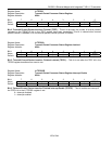
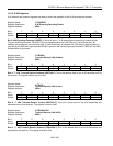
Bits 0 – 6: Transmit Errored Packet Insertion Rate (TPER[6:0]) – These seven bits indicate the rate at which
errored packets are to be output. One out of every x * 10
y
packets is to be an errored packet. TPER[3:0] is the
value x, and TPER[6:4] is the value y which has a maximum value of 6. If TPER[3:0] has a value of 0h errored
packet insertion is disabled. If TPER[6:4] has a value of 6xh or 7xh the errored packet rate is x * 10
6
. A TPER[6:0]
value of 01h results in every packet being errored. A TPER[6:0] value of 0Fh results in every 15
th
packet being
errored. A TPER[6:0] value of 11h results in every 10
th
packet being errored.
To initiate automatic error insertion, use the following routine:
1) Configure LI.TEPLC and LI.TEPHC for the desired error insertion mode.
2) Write the LI.TPPCL.TIAEI bit to 1. Note that this bit is write-only.
3) If not using continuous error insertion (LI.TPELC is not equal to FFh), the user should monitor the
LI.TPPSR.TEPF bit for completion of the error insertion. If interrupt on completion of error insertion is
enabled (LI.TPPSRIE.TEPFIE = 1), the user only needs to wait for the interrupt condition.
4) Proceed with the cleanup routine listed below.
Cleanup routine:
1) Write LI.TEPLC and LI.TEPHC each to 00h.
2) Write the LI.TPPCL.TIAEI bit to 0.