


DS33R11 Ethernet Mapper with Integrated T1/E1/J1 Transceiver
134 of 344
11.2 Global Register Definitions for Ethernet Mapper
Functions contained in the global registers include: framer reset, LIU reset, device ID, and BERT interrupt status.
These registers are preserved to provide code compatibility with the multiport devices in this product family. The
global registers bit descriptions are presented below.
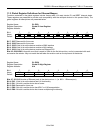
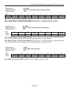
Register Name:
GL.IDRL
Register Description:
Global ID Low Register
Register Address:
00h
Bit # 7 6 5 4 3 2 1 0
Name ID07 ID06 ID05 ID04 ID03 ID02 ID01 ID00
Default 0 0 1 1 0 0 0 0
Bit 7: ID07 Reserved for future use
Bit 6: ID06 Reserved for future use
Bit 5: ID05 If this bit is set the device contains a RMII interface
Bit 4: ID04 If this bit is set the device contains a MII interface
Bit 3: ID03 If this bit is set the device contains an Ethernet PHY
Bits 0-2: ID00-ID02 A three-bit count that is equal to 000b for the first die revision, and is incremented with each
successive die revision. May not match the two-letter die revision code on the top brand of the device.
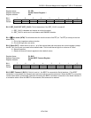
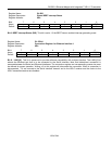
Register Name:
GL.IDRH
Register Description:
Global ID High Register
Register Address:
01h
Bit # 7 6 5 4 3 2 1 0
Name
ID15 ID14 ID13 ID12 ID11 ID10 ID09 ID08
Default 0 0 0 0 0 0 1 0
Bits 5-7: ID13-15 Number of Ethernet ports in the device minus 1. (i.e. 000 = 1 Ethernet port)
Bit 4: ID12 If this bit is set the device has LIU functionality
Bit 3: ID11 If this bit is set the device has a framer
Bit 2: ID10 Reserved for future use
Bit 1: ID09 If this bit is set the device has HDLC or X.86 encapsulation
Bit 0: ID08 If this bit is set the device has inverse multiplexing functionality