


DS33R11 Ethernet Mapper with Integrated T1/E1/J1 Transceiver
257 of 344
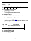
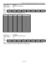
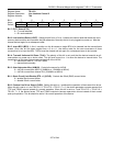
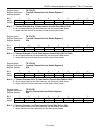
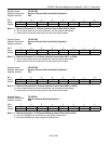
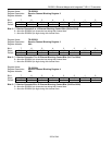
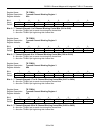
Register Name:
TR.LIC2
Register Description:
Line Interface Control 2
Register Address:
79h
Bit # 7 6 5 4 3 2 1 0
Name ETS LIRST IBPV TUA1 JAMUX — SCLD CLDS
Default 0 0 0 0 0 0 0 0
Bit 7: E1/T1 Select (ETS)
0 = T1 mode selected
1 = E1 mode selected
Bit 6: Line Interface Reset (LIRST). Setting this bit from a 0 to a 1 initiates an internal reset that resets the clock
recovery state machine and recenters the jitter attenuator. Normally this bit is only toggled on power-up. Must be
cleared and set again for a subsequent reset.
Bit 5: Insert BPV (IBPV). A 0-to-1 transition on this bit causes a single BPV to be inserted into the transmit data
stream. Once this bit has been toggled from a 0 to a 1, the device waits for the next occurrence of three
consecutive 1s to insert the BPV. This bit must be cleared and set again for a subsequent error to be inserted.
Bit 4: Transmit Unframed All Ones (TUA1). The polarity of this bit is set such that the device transmits an all-
ones pattern on power-up or device reset. This bit must be set to a 1 to allow the device to transmit data. The
transmission of this data pattern is always timed off of the JACLK.
0 = transmit all ones at TTIP and TRING
1 = transmit data normally
Bit 3: Jitter Attenuator Mux (JAMUX). Controls the source for JACLK.
0 = JACLK sourced from MCLK (2.048MHz or 1.544MHz at MCLK)
1 = JACLK sourced from internal PLL (2.048MHz at MCLK)
Bit 1: Short-Circuit Limit Disable (ETS = 1) (SCLD). Controls the 50mA (RMS) current limiter.
0 = enable 50mA current limiter
1 = disable 50mA current limiter
Bit 0: Custom Line Driver Select (CLDS). Setting this bit to a 1 redefines the operation of the transmit line driver.
When this bit is set to a 1 and TR.LIC1.5 = TR.LIC1.6 = TR.LIC1.7 = 0, the device generates a square wave at the
TTIP and TRING outputs instead of a normal waveform. When this bit is set to a 1 and TR.LIC1.5 = TR.LIC1.6 =
TR.LIC1.7 ≠ 0, the device forces TTIP and TRING outputs to become open-drain drivers instead of their normal
push-pull operation. This bit should be set to 0 for normal operation of the device.