


DS33R11 Ethernet Mapper with Integrated T1/E1/J1 Transceiver
220 of 344
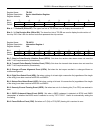
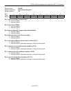
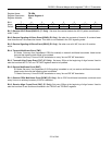
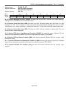
Register Name:
TR.IMR3
Register Description:
Interrupt Mask Register 3
Register Address:
1Bh
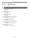
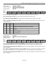
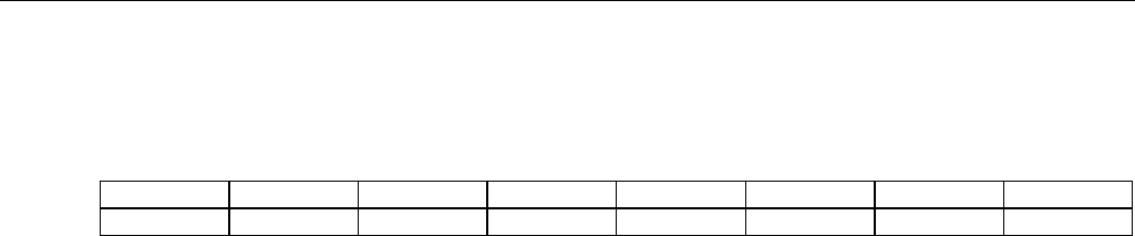
Bit # 7 6 5 4 3 2 1 0
Name LSPARE LDN LUP LOTC LORC V52LNK RDMA RRA
Default 0 0 0 0 0 0 0 0
Bit 7: Spare Code Detected Condition (LSPARE)
0 = interrupt masked
1 = interrupt enabled—interrupts on rising and falling edges
Bit 6: Loop-Down Code-Detected Condition (LDN)
0 = interrupt masked
1 = interrupt enabled—interrupts on rising and falling edges
Bit 5: Loop-Up Code-Detected Condition (LUP)
0 = interrupt masked
1 = interrupt enabled—interrupts on rising and falling edges
Bit 4: Loss-of-Transmit Clock Condition (LOTC)
0 = interrupt masked
1 = interrupt enabled—interrupts on rising and falling edges
Bit 3: Loss-of-Receive Clock Condition (LORC)
0 = interrupt masked
1 = interrupt enabled—interrupts on rising and falling edges
Bit 2: V5.2 Link Detected Condition (V52LNK)
0 = interrupt masked
1 = interrupt enabled—interrupts on rising and falling edges
Bit 1: Receive Distant MF Alarm Condition (RDMA)
0 = interrupt masked
1 = interrupt enabled—interrupts on rising and falling edges
Bit 0: Receive Remote Alarm Condition (RRA)
0 = interrupt masked
1 = interrupt enabled—interrupts on rising and falling edges