DS33R11 Ethernet Mapper with Integrated T1/E1/J1 Transceiver
252 of 344
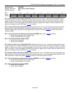
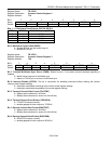
Register Name:
TR.CCR2
Register Description:
Common Control Register 2
Register Address:
71h
Bit # 7 6 5 4 3 2 1 0
Name — — — — — BPCS1 BPCS0 BPEN
Default 0 0 0 0 0 0 0 0
Bits 1 – 2: Backplane Clock Selects (BPCS0, BPCS1)
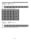
BPCS1 BPCS0 BPCLK Frequency (MHz)
0 0 16.384
0 1 8.192
1 0 4.096
1 1 2.048
Bit 0: Backplane Clock Enable (BPEN)
0 = disable BPCLK pin (pin held at logic 0)
1 = enable BPCLK pin
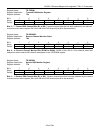
Register Name:
TR.CCR3
Register Description:
Common Control Register 3
Register Address:
72h
Bit # 7 6 5 4 3 2 1 0
Name TMSS INTDIS — — TDATFMT TGPCKEN RDATFMT RGPCKEN
Default 0 0 0 0 0 0 0 0
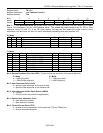
Bit 7: Transmit Multiframe Sync Source (TMSS). Should be set = 0 only when transmit hardware signaling is
enabled.
0 = elastic store is source of multiframe sync
1 = framer or TSYNC pin is source of multiframe sync
Bit 6: Interrupt Disable (INTDIS). This bit is convenient for disabling interrupts without altering the various
interrupt mask register settings.
0 = interrupts are enabled according to the various mask register settings
1 = interrupts are disabled regardless of the mask register settings
Bit 3: Transmit Channel-Data Format (TDATFMT)
0 = 64kbps (data contained in all 8 bits)
1 = 56kbps (data contained in seven out of the 8 bits)
Bit 2: Transmit Gapped-Clock Enable (TGPCKEN)
0 = TCHCLK functions normally
1 = enable gapped bit-clock output on TCHCLK
Bit 1: Receive Channel-Data Format (RDATFMT)
0 = 64kbps (data contained in all 8 bits)
1 = 56kbps (data contained in seven out of the 8 bits)
Bit 0: Receive Gapped-Clock Enable (RGPCKEN)
0 = RCHCLK functions normally
1 = enable gapped bit-clock output on RCHCLK


