


DS33R11 Ethernet Mapper with Integrated T1/E1/J1 Transceiver
279 of 344
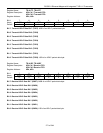
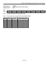
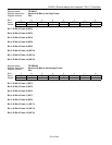
Register Name:
TR.TFDL
Register Description:
Transmit FDL Register
Register Address:
C1h
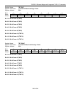
Bit # 7 6 5 4 3 2 1 0
Name TFDL7 TFDL6 TFDL5 TFDL4 TFDL3 TFDL2 TFDL1 TFDL0
Default 0 0 0 0 0 0 0 0
Note: Also used to insert Fs framing pattern in D4 framing mode.
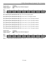
The transmit FDL register (TR.TFDL) contains the FDL information that is to be inserted on a byte basis into the
outgoing T1 data stream. The LSB is transmitted first.
Bit 7: Transmit FDL Bit 7 (TFDL7). MSB of the transmit FDL code.
Bit 6: Transmit FDL Bit 6 (TFDL6)
Bit 5: Transmit FDL Bit 5 (TFDL5)
Bit 4: Transmit FDL Bit 4 (TFDL4)
Bit 3: Transmit FDL Bit 3 (TFDL3)
Bit 2: Transmit FDL Bit 2 (TFDL2)
Bit 1: Transmit FDL Bit 1 (TFDL1)
Bit 0: Transmit FDL Bit 0 (TFDL0). LSB of the transmit FDL code.
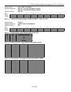
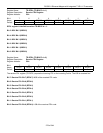
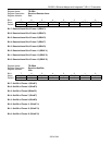
Register Name:
TR.RFDLM1, TR.RFDLM2
Register Description:
Receive FDL Match Register 1
Receive FDL Match Register 2
Register Address:
C2h, C3h
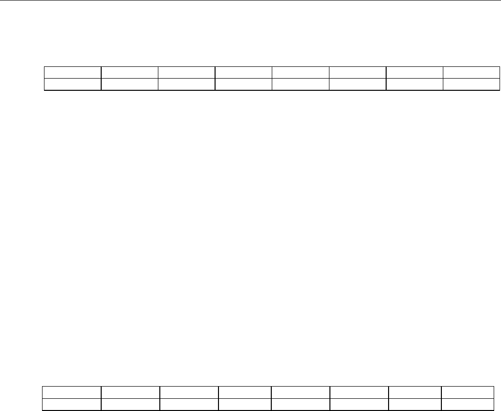
Bit # 7 6 5 4 3 2 1 0
Name RFDLM7 RFDLM6 RFDLM5 RFDLM4 RFDLM3 RFDLM2 RFDLM1 RFDLM0
Default 0 0 0 0 0 0 0 0
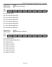
Bit 7: Receive FDL Match Bit 7 (RFDLM7). MSB of the FDL match code.
Bit 6: Receive FDL Match Bit 6 (RFDLM6)
Bit 5: Receive FDL Match Bit 5 (RFDLM5)
Bit 4: Receive FDL Match Bit 4 (RFDLM4)
Bit 3: Receive FDL Match Bit 3 (RFDLM3)
Bit 2: Receive FDL Match Bit 2 (RFDLM2)
Bit 1: Receive FDL Match Bit 1 (RFDLM1)
Bit 0: Receive FDL Match Bit 0 (RFDLM0). LSB of the FDL match code.