


DS33R11 Ethernet Mapper with Integrated T1/E1/J1 Transceiver
214 of 344
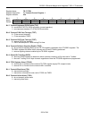
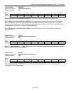
Register Name:
TR.INFO3
Register Description:
Information Register 3
Register Address:
12h
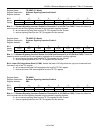
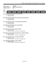
Bit # 7 6 5 4 3 2 1 0
Name — — — — — CRCRC FASRC CASRC
Default 0 0 0 0 0 0 0 0
Bit 2: CRC Resync Criteria Met Event (CRCRC). Set when 915/1000 codewords are received in error.
Bit 1: FAS Resync Criteria Met Event (FASRC). Set when three consecutive FAS words are received in error.
Note: During a CRC resync the FAS synchronizer is brought online to verify the FAS alignment. If during this
process an FAS emulator exists, the FAS synchronizer may temporarily align to the emulator. The FASRC will go
active indicating a search for a valid FAS has been activated.
Bit 0: CAS Resync Criteria Met Event (CASRC). Set when two consecutive CAS MF alignment words are
received in error.
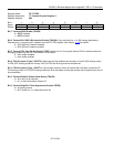
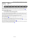
Register Name:
TR.IIR1
Register Description:
Interrupt Information Register 1
Register Address:
14h
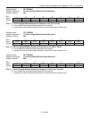
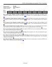
Bit # 7 6 5 4 3 2 1 0
Name SR8 SR7 SR6 SR5 SR4 SR3 SR2 SR1
Default 0 0 0 0 0 0 0 0
Bits 0 – 7: Status Register 1 – 8 (SR1–SR8). When set to 1, these bits indicate that an enabled interrupt is active
in the associated T1/E1/J1 status register.
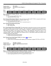
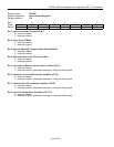
Register Name:
TR.IIR2
Register Description:
Interrupt Information Register 2
Register Address:
15h
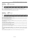
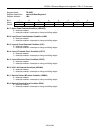
Bit # 7 6 5 4 3 2 1 0
Name — — — — — — — SR9
Default 0 0 0 0 0 0 0 0
Bits 0: Status Register 9 (SR9). When set to 1, this bit indicates that an enabled interrupt is active in the
associated T1/E1/J1 status register.