


DS33R11 Ethernet Mapper with Integrated T1/E1/J1 Transceiver
104 of 344
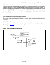
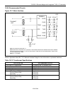
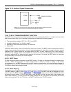
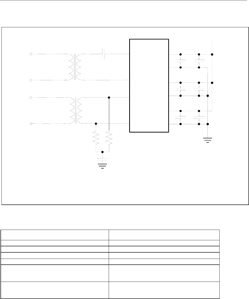
10.24 Recommended Circuits
Figure 10-7. Basic Interface
Refer to Application Note 324: T1/E1 Network Interface Design for more information on protected interfaces.
TTIP
TRING
RTIP
RRING
DVDD
TVDD
RVDD
VDD
DVSS
TVSS
RVSS
DS33R11
R R
2:1
1:1
C
0.1μF
0.1μF
0.1μF
0.01μF
TRANSMIT
LINE
RECEIVE
LINE
0.1μF
10μF
10μF
+
+
NOTE 1: ALL RESISTOR VALUES ARE ±1%.
NOTE 2: RESISTORS R SHOULD BE SET TO 60Ω EACH IF THE INTERNAL RECEIVE-SIDE TERMINATION FEATURE IS ENABLED.
WHEN THIS FEATURE IS DISABLED, R = 37.5Ω FOR 75Ω COAXIAL E1 LINES, 60Ω FOR 120Ω TWISTED-PAIR E1 LINES, OR 50Ω
FOR 100Ω TWISTED-PAIR T1 LINES.
NOTE 3: C = 1μF CERAMIC.
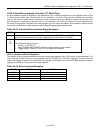
Table 10-13. Transformer Specifications
SPECIFICATION RECOMMENDED VALUE
Turns Ratio 3.3V Applications 1:1 (receive) and 1:2 (transmit) ±2%
Primary Inductance
600μH (min)
Leakage Inductance
1.0μH (max)
Intertwining Capacitance 40pF (max)
Transmit Transformer DC Resistance
Primary (Device Side)
Secondary
1.0Ω (max)
2.0Ω (max)
Receive Transformer DC Resistance
Primary (Device Side) 1.2Ω (max)
Secondary 1.2Ω (max)