


Rev. 1.00, 05/04, page 82 of 544
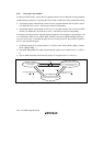
5.6.2 Interrupt Control Mode 1
In interrupt control mode 1, mask control is applied to three levels for IRQ and on-chip peripheral
module interrupt requests by comparing the I and UI bits in CCR in the CPU, and the ICR setting.
• An interrupt request with interrupt control level 0 is accepted when the I bit in CCR is cleared
to 0. When the I bit is set to 1, the interrupt request is held pending
• An interrupt request with interrupt control level 1 is accepted when the I bit or UI bit in CCR is
cleared to 0. When both I and UI bits are set to 1, the interrupt request is held pending.
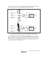
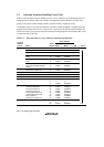
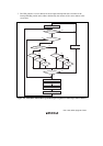
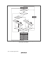
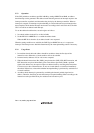
For instance, the state transition when the interrupt enable bit corresponding to each interrupt is set
to 1, and ICRA to ICRC are set to H'20, H'00, and H'00, respectively (IRQ2 and IRQ3 interrupts
are set to control level 1, and other interrupts are set to control level 0) is shown below. Figure 5.5
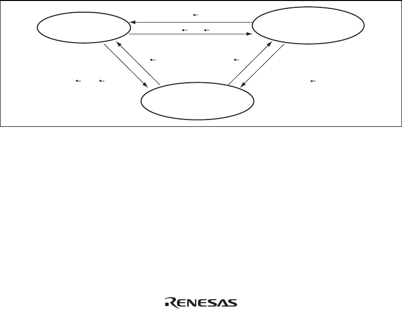
shows a state transition diagram.
• All interrupt requests are accepted when I = 0. (Priority order: NMI > IRQ2 > IRQ3 > address
break > IRQ0 > IRQ1 …)
• Only NMI, IRQ2, IRQ3 and address break interrupt requests are accepted when I = 1 and UI =
0.
• Only an NMI and address break interrupt request is accepted when I = 1 and UI = 1.
Only NMI and address break
interrupt requests are accepted
All interrupt requests
are accepted
Exception handling execution
or I 1, UI 1
I 0
I 1, UI 0
I 0UI 0
Exception handling
execution or UI 1
Only NMI, address break, IRQ2,
and IRQ3 interrupt requests
are accepted
Figure 5.5 State Transition in Interrupt Control Mode 1