


Rev. 1.00, 05/04, page 316 of 544
SDA
(master output)
SDA
(slave output)
21
4
3
65
8
7
1
2
99
A
A
Bit 7
Bit 6
Bit 5
Bit 4
Bit 3
Bit 2
Bit 1
Bit 0
Bit 7
Bit 6
IRTR
ICDRF
ICDRR
SCL
(master output)
Master transmit mode
Master receive mode
Data 1
Data 1
Data 2
[1]
TRS=0
clear
[2] IRIC read
(Dummy read)
[1] IRIC clear
SCL is fixed low until ICDR is read SCL is fixed low until ICDR is read
[4] IRIC clear
User processing
IRIC
[3]
[5] ICDR read
(Data 1)
Undefined value
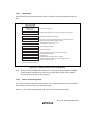
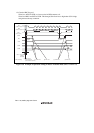
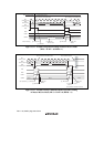
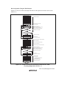
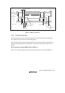
Figure 13.11 Example of Operation Timing in Master Receive Mode
(MLS = WAIT = 0, HNDS = 1)
SDA
(master output)
SDA
(slave output)
21
4
3
65
8
7
9978
A
A
Bit 7Bit 1
Bit 6
Bit 5
Bit 4
Bit 3
Bit 2
Bit 1
IRIC
ICDRF
ICDRR
SCL
(master output)
Data 3
Data 2
Data 1 Data 2
Data 3
[9] IRIC clear
User processing
IRTR
[8] [3]
Bit 0
[11]
Set BBSY = 0 and
SCP = 0
(Stop condition instruction issuance)
[4] IRIC clear [7]
ICDR read
(Data 2)
[10]
ICDR read
(Data 3)
[6]
Set ACKB = 1
Bit 0
Stop condition generation
SCL is fixed low until ICDR is read
SCL is fixed low until
stop condition is issued
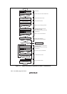
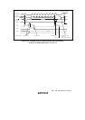
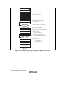
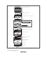
Figure 13.12 Example of Stop Condition Issuance Operation Timing
in Master Receive Mode (MLS = WAIT = 0, HNDS = 1)