


Rev. 1.00, 05/04, page 10 of 544
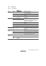
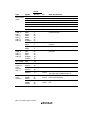
Pin No.
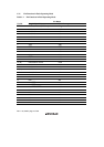
Type Symbol TFP-144 I/O Name and Function
FTCI 78 Input The counter clock input pin.
FTOA 79 Output The output compare A output pin.
FTOB 84 Output The output compare B output pin.
FTIA 80 Input The input capture A input pin.
FTIB 81 Input The input capture B input pin.
FTIC 82 Input The input capture C input pin.
16-bit free-
running timer
(FRT)
FTID 83 Input The input capture D input pin.
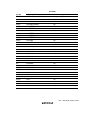
TMO0
TMO1
TMOX
TMOY*
TMOA
TMOB
ExTMOX*
137
3
85
43
48
47
44
Output The waveform output pins for the output
compare function.
TMCI0
TMCI1
136
2
Input Input pins for the external clock input to
counters.
8-bit timer
(TMR_0,
TMR_1,
TMR_X,
TMR_Y,
TMR_A,
TMR_B)
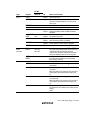
TMRI0
TMRI1
138
4
Input The counter reset input pins.
8-bit timer
(TMR_X,
TMR_Y,
TMR_A,
TMR_B)
TMIX
TMIY
TMIA
TMIB
ExTMIX*
ExTMIY*
78
80
50
49
46
45
Input The counter event input and counter reset
input pins.
8-bit PWM
timer (PWM)
PW7 to
PW0
104 to 110,
112
Output PWM timer pulse output pins.
TxD1
ExTxD1*
133
16
Output Transmit data output pins.
RxD1
ExRxD1*
134
15
Input Receive data input pins.
Serial
communi-
cation
interface
(SCI_1)
SCK1
ExSCK1*
135
14
Input/
Output
Clock input/output pins.
The output type is NMOS push-pull.
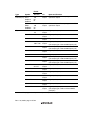
PS2AC
PS2BC
PS2CC
39
37
34
Input/
Output
Keyboard buffer controller synchronization
clock input/output pins.
Keyboard
buffer
controller
PS2AD
PS2BD
PS2CD
38
35
33
Input/
Output
Keyboard buffer controller data input/output
pins.