


Rev. 1.00, 05/04, page 448 of 544
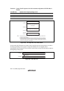
18.8.2 Erase/Erase-Verify
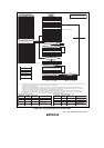
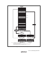
When erasing flash memory, the erase/erase-verify flowchart shown in figure 18.10 should be
followed.
1. Prewriting (setting erase block data to all 0) is not necessary.
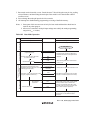
2. Erasing is performed in block units. Make only a single-block specification in erase block
registers 1 and 2 (EBR1 and EBR2). To erase multiple blocks, each block must be erased in
turn.
3. The time during which the E bit is set to 1 is the flash memory erase time.
4. The watchdog timer (WDT) is set to prevent overprogramming due to program runaway, etc.
An overflow cycle of approximately (y + z + α + β) ms is allowed.
5. For a dummy write to a verify address, write 1-byte data H'FF to an address whose lower two
bits are B'00. Verify data can be read in longwords from the address to which a dummy write
was performed.
6. If the read data is unerased, set erase mode again, and repeat the erase/erase-verify sequence as
before. The maximum number of repetitions of the erase/erase-verify sequence is N.