


Rev. 1.00, 05/04, page 321 of 544
SDA
(master output)
SDA
(slave output)
21
4
3
65
8
7
998
A
A
Bit 7Bit 0
Bit 6
Bit 5
Bit 4
Bit 3
Bit 2
Bit 1
IRIC
IRTR
ICDR
SCL
(master output)
Data 3
Data 2
Data 1 Data 2
Data 3
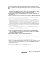
[6] IRIC clear
[8]
Wait for one clock pulse
[11] IRIC clear
[14] IRIC clear
[16] ICDR read
(Data 3)
User processing
[12]
[3]
[10] ICDR read (Data 2)
[9]
Set TRS=1
[7]
Set ACKB=1
[15]
WAIT cleared
to 0, IRIC clear
[17] Stop condition
issuance
Bit 0
Stop condition generation
[13]
IRTR=1
[13]
IRTR=0
[12]
[4]
IRTR=1
[4]
IRTR=0
[3]
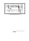
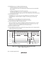
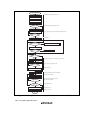
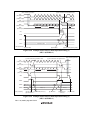
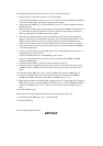
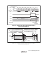
Figure 13.16 Example of Stop Condition Issuance Timing in Master Receive Mode
(MLS = ACKB = 0, WAIT = 1)
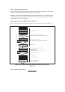
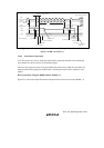
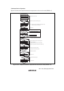
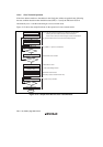
13.4.5 Slave Receive Operation
In I
2
C bus format slave receive mode, the master device outputs the transmit clock and transmit
data, and the slave device returns an acknowledge signal.
The slave device operates as the device specified by the master device when the slave address in
the first frame following the start condition that is issued by the master device matches its own
address.
Receive Operation Using the HNDS Function (HNDS = 1):
Figure 13.17 shows the sample flowchart for the operations in slave receive mode (HNDS = 1).