


Rev. 1.00, 05/04, page 444 of 544
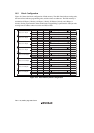
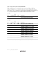
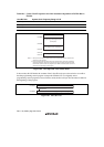
Table 18.6 System Clock Frequencies for which Automatic Adjustment of LSI Bit Rate is
Possible
Host Bit Rate System Clock Frequency Range of LSI
19200 bps 8 to 10 MHz
9600 bps 4 to 10 MHz
4800 bps 4 to 10 MHz
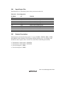
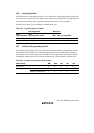
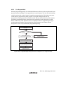
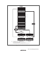
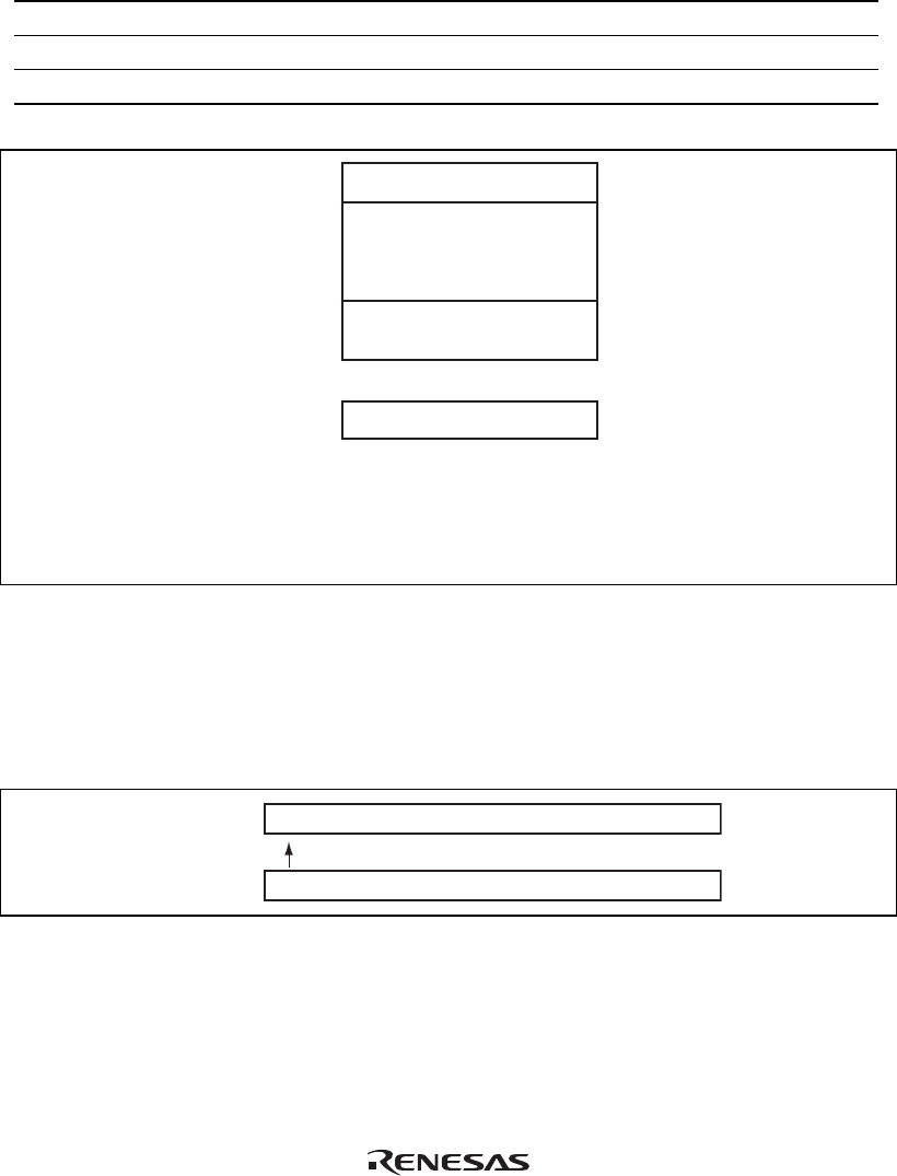
Boot program area*
2
(128 bytes)
H'FFFF7F
H'FFFF00
H'FFEFFF
H'FFE880
H'FFE088
H'FFE080
ID code area*
1
Programming control program area*
1
(2040 bytes)
Boot program area*
2
(1920 bytes)
Notes: 1. Some parts of this area are reserved only for boot mode and therefore should not be
used for any other purpose.
2. The boot program area and area which is not used cannot be used until a transition is
made to the execution state for the programming control program transferred to RAM.
Note that the contents of the boot program area in RAM are remained after a branch is
made to the programming control program.
Figure 18.6 On-Chip RAM Area in Boot Mode
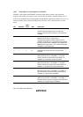
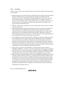
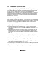
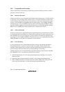
In boot mode, this LSI checks the contents of the 8-byte ID code area as shown below to confirm
that the programming control program corresponds with this LSI. To originally write a
programming control program to be used in boot mode, the above 8-byte ID code must be added at
the beginning of the program.
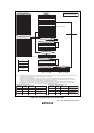
H'FFE080
H'FFE088
3040 FE 64 66 32 31 31
Instruction codes of the programming control program
(Product ID)
Figure 18.7 ID Code Area