


Rev. 1.00, 05/04, page 528 of 544
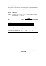
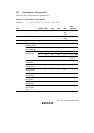
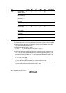
Item Symbol Min. Typ. Max. Unit
Test
Conditions
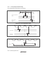
Wait time after
SWE-bit setting*
1
x 1 — — µs
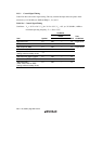
Wait time after
ESU-bit setting*
1
y 100 — — µs
Wait time after
E-bit setting*
1
, *
6
z 10 — 100 ms
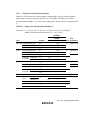
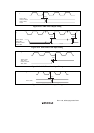
Wait time after
E-bit clear*
1
α 10 — — µs
Wait time after
ESU-bit clear*
1
β 10 — — µs
Wait time after
EV-bit setting*
1
γ 20 — — µs
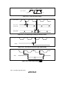
Wait time after
dummy write*
1
ε 2 — — µs
Wait time after
EV-bit clear*
1
η 4 — — µs
Wait time after
SWE-bit clear*
1
θ 100 — — µs
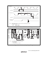
Erase
Maximum erase
count*
1
, *
6
, *
7
N — — 120 times
Notes: 1. Set the times according to the program/erase algorithms.
2. Programming time per 128 bytes (Shows the total period for which the P-bit in FLMCR1
is set. It does not include the programming verification time.)
3. Block erase time (Shows the total period for which the E-bit in FLMCR1 is set. It does
not include the erase verification time.)
4. Maximum programming time (t
P
(max))
t
P
(max) = (wait time after P-bit setting (z1) + (z3)) × 6
+ wait time after P-bit setting (z2) × ((N) – 6)
5. The maximum number of writes (N) should be set according to the actual set value of
z1, z2 and z3 to allow programming within the maximum programming time (t
P
(max)).
The wait time after P-bit setting (z1, z2, and z3) should be alternated according to the
number of writes (n) as follows:
1 ≤ n ≤ 6 z1 = 30µs, z3 = 10µs
7 ≤ n ≤ 1000 z2 = 200µs
6. Maximum erase time (t
E
(max))
t
E
(max) = Wait time after E-bit setting (z) × maximum erase count (N)
7. The maximum number of erases (N) should be set according to the actual set value of z
to allow erasing within the maximum erase time (t
E
(max)).